Engineering Graphics: Unit II (c): Projections of Straight Lines
Projections of a Straight line contained by a Profile Plane
Engineering Graphics (EG)
In all those previous examples of straight lines inclined to both the planes, sum of true inclinations was less than 90°
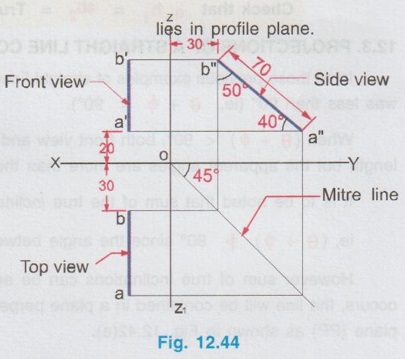
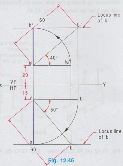
PROJECTIONS OF A STRAIGHT LINE CONTAINED BY A PROFILE PLANE In all those previous examples of straight lines inclined to both the planes, sum of true inclinations was less than 90° (ie, θ + ϕ < 90°). When (θ + ϕ) < 90°, both front view and top view will be straight lines shorter than the true length but the apparent angles are more than the true inclinations. (ie., α > θ; β > ϕ). It is to be noted that sum of the true inclinations can never be more than 90°, ie, (θ + ϕ) However sum of true inclinations can be equal to 90° (ie, θ + ϕ = 90°) When this case occurs, the line will be contained in a plane perpendicular to both the reference planes, called profile plane (PP) as shown in Fig. 12.42(a). When the line AB with θ + ϕ = 90° is viewed in the directions for front view and top view, the projections will be straight line perpendicular to the reference axis XY. Rotating the HP to 90° in clockwise direction and eliminating the size of the planes, the projections are drawn as shown in Fig. 12.42(b). The front view and top view can be directly drawn as shown in Fig. 12.42(b) or it may also be developed by drawing the side view (ie, Projection on profile plane) first and projecting it for front view and top view as shown in Fig. 12.43. Example 21: A line AB of 70 mm long is resting in the first quadrant in such a way that the end A is 20 mm above HP and the end B is 30 mm infront of VP. The line is inclined at 40° to HP and 50° to VP. Draw the projections. Given l = 70 mm ; θ = 40°; ϕ = 50° Here θ + ϕ = 90°, hence the line The projections are shown in Fig. 12.44. 1. Draw the reference axis XY and locate the origin at O. 2. Draw the side view a" b" of length 70 mm. (Note that in side view the true length and the angles θ and ϕ are seen since the line AB is parallel to the profile plane), such a way that the point a" is 20 mm above XY and the point b" is 30 mm from OZ. which represents height of the point A above HP and distance of the point B from VP respectively. 3. Draw the Mitre line at 45° through the point O. 4. Draw the vertical projectors through the points a" and b" to intersect the mitre line and then draw the horizontal projectors from the points of intersection. 5. At a convenient distance from OZ draw a vertical line to intersect the horizontal projectors drawn from the Mitre line. (This distance is the distance of AB line from profile plane. If it is not given in the problem, it can be assumed suitably). Let the points of intersection be a and b. ab waiv represents the top view. 7. Project the topview above XY to cut the horizontal projector drawn from the points a" and b" at a' and b' respectively. a' b' be represents the front view. Note: Front view and Top view can also be drawn directly without drawing the side view. Note: When θ + ϕ = 90° and true length of line is known, it can be solved as Type I problem, as illustrated below. Example 22: A line AB of 60mm long has its end A 20mm above HP and 15mm infront of VP. The line is inclined at 40° to HP and 50° to VP. Draw its projections. Given l = 60 mm; θ = 40°; ϕ = 50°. Here θ + ϕ = 40 + 50 = 90°. Hence the final projections (Both front view and top view) are straight lines, perpendicular to XY and lie on a common projector. However this problem can be solved as type I problem (0) (For construction procedure refer example 11). Projections of the given line is shown in Fig. 12.45. a'b1' = ab2 = True length = 60 mm a'b' = Front view, ab = Top view Note that when θ + ϕ = 90; both the apparent angles α and β are 90°![]() 90° since the angle between HP and VP is 90°.
90° since the angle between HP and VP is 90°.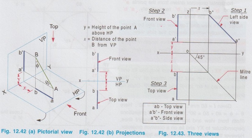
Engineering Graphics: Unit II (c): Projections of Straight Lines : Tag: : Engineering Graphics (EG) - Projections of a Straight line contained by a Profile Plane
Related Topics
Related Subjects

Engineering Graphics
GE3251 eg 2nd semester | 2021 Regulation | 2nd Semester Common to all Dept 2021 Regulation