Hydraulics and Pneumatics: Unit IV: Pneumatic and Electro Pneumatic Systems
programming the plc
Pneumatic and Electro Pneumatic Systems - Hydraulics and Pneumatics
The basic form of programming commonly used with PLCs is ladder programming.
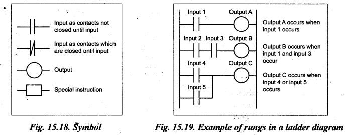
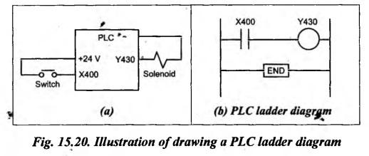
PROGRAMMING THE PLC • The basic form of programming commonly used with PLCs is ladder programming. • PLC programming based on the use of ladder diagrams involves writing a program in a similar manner to drawing a switching circuit. • The ladder diagram consists of two vertical lines representing the power lines. Circuits are connected as horizontal lines. i.e., the rungs of the ladder, between these two verticals. • Fig.15.18 shows the basic standard symbols that are used. • Fig.15.19 shows an example of rungs in a ladder diagram. Fig. 15.19. Example of rungs in a ladder diagram In drawing the circuit line for a rung, inputs must always precede outputs and there must be at least one output on each line. Each rung start with an input or a series of inputs and end with an output. The inputs and outputs are numbered, the notation used depending on the manufacturer. For example, the Mitsubishi F series of PLCs precedes input elements by an X and output elements by a Y and uses the following numbers : Inputs X400–407, 410–413 X500-507, 510-513 (24 possible inputs) Outputs Y430-437 Y530-537 (16 possible outputs) Consider an example of a solenoid valve which opens to allow water to enter a vessel. This situation, where the output from the PLC is to energise a solenoid when a normally open start switch connected to the input is being closed, is shown in Fig.15.20(a). The PLC ladder diagram for the situation is shown in Fig.15.20(b). Starting with the input, we have the normally open symbol ||. This might have an input address X400. The line terminates with the output, the solenoid, with the symbol O. This might have the output address Y430. To indicate the end of the program the end rung is marked. When the switch is closed the solenoid is activated.1. What is mean by Ladder Programming ?
2. PLC Ladder Symbols
3. Construction
4. Illustration of Drawing a PLC Ladder Diagram
Hydraulics and Pneumatics: Unit IV: Pneumatic and Electro Pneumatic Systems : Tag: : Pneumatic and Electro Pneumatic Systems - Hydraulics and Pneumatics - programming the plc
Related Topics
Related Subjects

Hydraulics and Pneumatics
ME3492 4th semester Mechanical Dept | 2021 Regulation | 4th Semester Mechanical Dept 2021 Regulation