Engineering Graphics: Unit V (a): Isometric Projection
Procedure for Drawing Isometric Projection
Box Method, Co-ordinate or Offset method | Engineering Graphics (EG)
Isometric projection of an object can be drawn by any one or a combination of the following methods, after a thorough understanding of characteristics of lines in an isometric projection, explained in previous article.
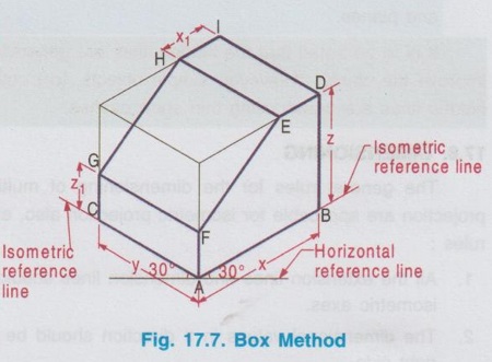
PROCEDURE FOR DRAWING ISOMETRIC PROJECTION: Isometric projection of an object can be drawn by any one or a combination of the following methods, after a thorough understanding of characteristics of lines in an isometric projection, explained in previous article. 1. Box Method 2. Co-ordinate (or) Offset method 1. Box Method Consider an object shown in Fig. 17.6, to be shown in Isometric projection. (Here for convenience, the pictorial view is taken. In general orthographic projections will be given, using which isometric projection to be drawn). In Box method, the object is assumed to be enclosed in a transparent rectangular box of size just to fit. Determine the overall dimensions of the box from the given pictorial view (or) orthographic projections. For the object shown in Fig. 17.6, the overall size of the isometric box is x × y × z. Convert these dimensions to isometric lengths either by using isometric scale or by multiplying with 0.816 using calculator and complete the isometric projection following the procedure given below. 1. Draw a horizontal reference line of short length and mark point A. 2. Draw the Isometric reference lines, two inclined lines at 30° each and a vertical line through the point A. Construct a box for the overall dimensions of the object (ie., length x, breadth y and depth z) and mark the points B, D, I and C. 4. On the vertical line drawn through A, locate the point F, at a distance of Z1 from A. 5. Draw a line parallel to AC line, through the point F to intersect the vertical line through C at G. 6. On the parallel lines passing through D and I locate the points E and H respectively at x1 distance apart. 7. Join the points H and G and join the reference points E and F. 8. Darken the edges of the object using thick line and dimension the object. The Isometric projection is shown in Fig. 17.7. Note: Box method is best suited for the objects containing more number of lines and planes parallel to the three isometric axes. 2. Offset Method In offset method (also called as co-ordinate method) one of the three isometric planes (top, left or right) is taken as the reference plane and the end points of the non- isometric lines are marked along an axis perpendicular to the reference plane. The pictorial view shown in Fig. 17.6 is drawn in isometric projection by off-set method and shown in Fig. 17.8. The step by step procedure is : 1. Draw a horizontal reference line of short length and mark point A. 2. Draw the isometric reference axes, two inclined lines at 30° each and a vertical line through the point A. 3. Construct the right isometric plane ABDEFA as below. i) Locate the point B such that AB = x. ii) Draw vertical lines AF and BD of heights Z1 and Z respectively. iii) Draw a line DE of length x1 and parallel to AB. iv) Join the points E and F. 4. Draw the lines through the points A, F, E and D of length y parallel to left isometric axis AC, to locate the points C, G, H and I respectively and join these points. Note that in offset method also the actual measurements are to be converted into isometric (length either by multiplying with 0.816 or by constructing isometric scale. Note: Offset method is best suited for objects containing a large number of non-isometric lines and planes. It is to be noted that the hidden lines are generally omitted in isometric projection of objects to improve the clarity. However, simple objects, (or) objects requiring the drawing of hidden details, hidden lines are drawn using thin short dashes.

Engineering Graphics: Unit V (a): Isometric Projection : Tag: : Box Method, Co-ordinate or Offset method | Engineering Graphics (EG) - Procedure for Drawing Isometric Projection
Related Topics
Related Subjects

Engineering Graphics
GE3251 eg 2nd semester | 2021 Regulation | 2nd Semester Common to all Dept 2021 Regulation