Theory of Machines: Unit I: Kinematics of Mechanisms
problems for practice
Kinematics of Mechanisms - Theory of Machines
problems for practice: problems for practice
PROBLEMS FOR PRACTICE
On Velocity and Acceleration Analysis by Relative Velocity and Relative Acceleration Methods
1.
In a four-bar chain ABCD, AD is fixed and is 150 mm long. The crank AB 40 mm
long and rotates at 120 rpm clockwise, while the link CD = 80 mm oscillates
about D. BC and AD are of equal length. Find the angular velocity of link CD when
angle BAD = 60°.
[Ans.
4.8 rad/s (CW about D)].
2.
The dimensions and configuration of the four bar mechanism, shown in Fig.2.39
are as follows: P1A 300 mm; P1B = 360 mm; AB = 360 mm and
P1P2 = 600 mm. The angle AP1P2 =
60°. The crank P1A has an angular velocity of 10 rad/s and an
angular acceleration of 30 rad/s2, both clockwise. Determine the
angular velocity and angular accelerations of P2B and AB and the
velocity and acceleration of the joint B.
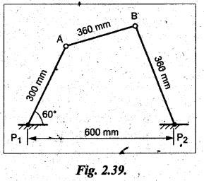
[Ans. 6.11 rad/s (CW); 5.83 rad/s (CCW);
2.2 m/s; 30 m/s2]
3.
In a four-bar chain ABCD, link AD is fixed and the crank AB rotates at 10 rad/s
clockwise. Lengths of links are AB = 60 mm; BC = CD = 70 mm; DA= 120 mm. When
angle DAB = 60 and both B and C lie on the same side of AD, find (1) angular
velocities of BC and CD; and (2) angular acceleration of BC and CD.
[Hint:
Refer Example 2.6]
[A.U.,
Apr/May 2011]
[Ans. 6.43 rad/s (CCW); 6.43 rad/s (CW); 10
rad/s2; 105 rad/s2]
4.
The crank and connecting rod of a theoretical steam engine are 0.5 m and 2 m
long respectively. The crank makes 180 rpm in the clockwise direction. When it
has turned 45° from the inner dead centre position, determine: (i) velocity of
piston; (ii) angular velocity of connecting rod; (iii) velocity of point E on
the connecting rod 1.5 m from the gudgeon pin; and (iv) position and linear
velocity of any point G on the connecting rod which has the least velocity
relative to crank shaft.
[A.U.,
Nov/Dec 2010]
[Hint:
Refer Example 2.8]
[Ans. (i) 8.15 m/s; (ii) 3.4 rad/s (ccw); (iii)
8.5 m/s; (iv) BG = 1.47 m; 8 m/s]
5.
A single slider-crank mechanism is shown in Fig.2.40. Determine the
acceleration at B & E and the angular acceleration of the link AB. The
crank rotates at 20 rad/s counter- clockwise.
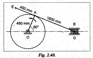
[Ans.
72 m/s2; 236 m/s2; 104 rad/s2]
6.
The dimensions of the various links of a mechanism as shown in Fig.2.41 are as
follows: OA = 80 mm; AC = CB - CD= 120 mm. If the crank OA rotates at 150 rpm
in the anti-clockwise direction, find, for the given configuration (i) velocity
and acceleration of B and D; (ii) rubbing velocity on the pin at C, if its
diameter is 20 mm and (iii) angular acceleration of the links AB and CD.
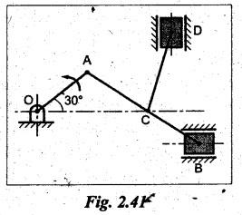
[Ans. 1.1 m/s; 0.37 m/s; 20.2 m/s2;
16.3 m/s2; 0.15 m/s; 34.6 rad/s2; 172.5 rad/s2]
7.
The dimensions of various links of a mechanism, as shown in Fig.2.42, are as
follows: AB = 30 mm; BC = 80 mm; CD = 45 mm; and CE = 120 mm.
The
crank AB rotates uniformly in the clockwise direction at 120 rpm. Draw the
velocity diagram for the given configuration of the mechanism and determine the
velocity of the slider E and angular velocities of the link BC, CD and CE. Also
draw a diagram shown in the extreme top and bottom positions of the crank DC
and the corresponding configurations of the mechanism. Find the length of each of
the strokes.
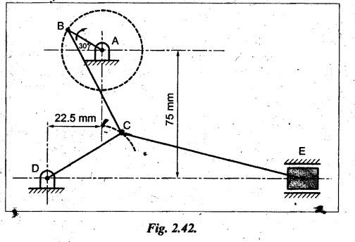
[Ans. 120 mm/s; 2.8 rad/s; 5.8 rad/s; 2
rad/s; 10 mm; 23 mm]
8.
In a Whitworth quick return motion mechanism, as shown in Fig.2.43, the
dimensions of various links are as follows: OQ = 100 mm; OA = 200 mm; BQ = 150
mm and BP 500 mm. If the crank OA turns at 120 rpm in clockwise direction and
makes an angle of 120° with OQ, find: (1) velocity of the block P and (2)
angular velocity of the slotted link BQ.
[Ans. 0.63 m/s; 6.3 rad/s]
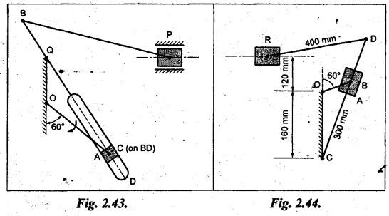
9.
In a quick-return mechanism, as shown in Fig.2.44, the driving crank OA is 60
mm long and rotates at a uniform speed of 200 rpm in a clockwise direction. For
the position shown, find (1) velocity of the ram R, (2) acceleration of the ram
R; and (3) acceleration of the sliding block A along the slotted bar CD.
[Ans. 1.3 m/s; 9 m/s2; 15 m/s2]
On Velocity Analysis by Instantaneous Centre Method
10.
In a pin jointed four-bar mechanism, AB = 300 mm, BC CD 360 mm, and AD = 600 =
= mm. The angle BAD 60°. The crank AB rotates uniformly at 100 rpm about 'A' in
clockwise direction. Locate all the instantaneous centres and find the angular
velocity of link BC.
[Ans. 6.282 rad/s].
11.
Locate all the instantaneous centres of the slider-crank mechanism. The length
of connecting rod AB is 400 mm and crank OB is 100 mm. If the crank rotates
clockwise with an angular velocity of 10 rad/s. Find: (i) velocity of slider A
and (ii) angular velocity of connecting rod AB if the crank has turned through
45° from IDC.
[Ans.
0.82 m/s, 1.78 rad/s]
12.
Locate all the instantaneous centres of the slider-crank mechanism, the length
of crank OB and connecting rod AB are 125 mm and 500 mm respectively. The crank
speed is 600 rpm clockwise. When the crank has turned 45° from the IDC.
Determine (i) velocity of slider A, and (ii) angular velocity of connecting rod
AB.
[Ans. 6.45 m/s, 10.8 rad/s]
On Velocity and Acceleration of Slider-Crank Mechanism by Analytical Method
13.
In a slider-crank mechanism, the length of the crank and connecting rod are 150
mm and 600 mm respectively. The crank position is 60° from IDC, the crankshaft
speed is 450 rpm'clockwise. Using analytical method, determine: (1) velocity
and acceleration of the slide and (2) angular velocity and angular acceleration
of the connecting rod.
[Ans. 6.9 m/s; 124.94 m/s2; 5.9
rad/s; 481 rad/s2]
14.
If the crank and connecting rod are 300 mm and 1 m long respectively and the
crank rotates at a constant speed of 200 rpm, determine (1) the crank angle at
which the maximum velocity occurs, and (2) maximum velocity of the piston.
[Ans. 75°; 6.54 m/s]
Theory of Machines: Unit I: Kinematics of Mechanisms : Tag: : Kinematics of Mechanisms - Theory of Machines - problems for practice
Related Topics
Related Subjects

Theory of Machines
ME3491 4th semester Mechanical Dept | 2021 Regulation | 4th Semester Mechanical Dept 2021 Regulation