Engineering Graphics: Unit V (a): Isometric Projection
Principles of Isometric Projection
Engineering Graphics (EG)
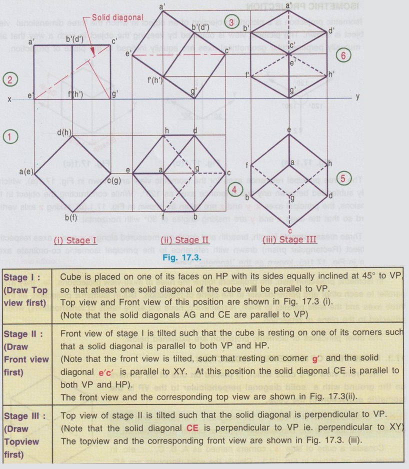
The Front view of a cube which is placed on one of its corners on the ground with a solid diagonal perpendicular to the VP is the Isometric projection of the cube.
PRINCIPLES OF ISOMETRIC PROJECTION The Front view of a cube which is placed on one of its corners on the ground with a solid diagonal perpendicular to the VP is the Isometric projection of the cube. Note: Solid diagonal of a cube is an imaginary line joining one of its corners at the top and the diametrically opposite corner at the bottom. Consider a cube of side `a', corners named as A, B, C, ..... etc. in pictorial view as shown in Fig. 17.2. Clearly the solid diagonals are AG, CE, BH and DF. Now the front view of cube is required with the position of one of the solid diagonals is perpendicular to VP and resting on the ground on one of its corners. The Final Front view obtained in Stage III is the Isometric projection of the cube, satisfying the conditions of one of its corners resting on the ground with a solid diagonal perpendicular to the VP. The Isometric projection (ie. Front view of Stage III in Fig. 17.3) is reproduced in Fig. 17.4 Note: In order to distinguish the isometric projection from multiview orthographic projections capital letters are used to denote the corners in Isometric projections. Referring the Fig. 17.4, the following principles of Isometric projection are derived: 1. Projectors are parallel to each other and perpendicular to the plane of projection. 2. All the edges and faces of the cube are equally oilouber to insp inclined to the plane of projection and hence they are seen as similar and equal rhombuses instead of as squares. 3. Three edges of the cube, CD, CB and CG are meeting at the point C. (i) These edges are mutually perpendicular to each other. (ii) These edges are equally inclined to the VP and therefore are equally foreshortened. (iii) These edges make equal angles of 120° with each other. (iv) The line CG is vertical and the other lines CB and CD make 30° angle with the horizontal. 4. All other lines representing the edges of the cubes are parallel to one or the other of the above three lines, ie., CD, CB and CG and equally foreshortened. 5. The diagonal BD of the top face is parallel to VP, shows its true length. However the diagonals which are not parallel to VP (ie., diagonal CA) is shortened.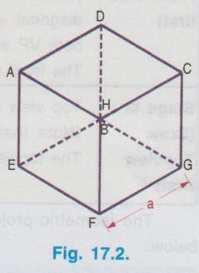

Engineering Graphics: Unit V (a): Isometric Projection : Tag: : Engineering Graphics (EG) - Principles of Isometric Projection
Related Topics
Related Subjects

Engineering Graphics
GE3251 eg 2nd semester | 2021 Regulation | 2nd Semester Common to all Dept 2021 Regulation