Hydraulics and Pneumatics: Unit II: Hydraulic Actuators and Control Components
pressure-compensated flow control valves
Hydraulic Actuators and Control Components - Hydraulics and Pneumatics
As we know the flow rate through any orifice depends upon the pressure difference between its inlet and outlet.
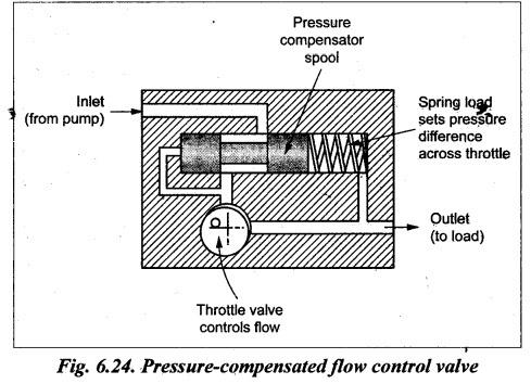
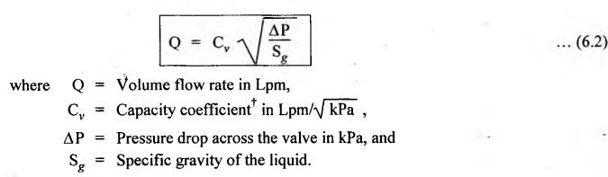
PRESSURE-COMPENSATED FLOW CONTROL VALVES As we know the flow rate through any orifice depends upon the pressure difference between its inlet and outlet. Therefore a constant pressure drop across the valve orifice is required to assure accurate flow control. This is accomplished with the pressure-compensated flow control valve. The construction and operation of a typical pressure-compensated flow control valve is illustrated in Fig.6.24. The valve actually has two main parts arranged in series. They are : 1. Throttle valves: Similar to a needle valve, the throttle valve has an orifice whose area can be adjusted by an external knob setting. This throttle valve setting determines the flow rate is to be controlled. 2. Pressure compensator: The pressure compensator spool controls the size of the inlet orifice and maintains a constant pressure drop across the throttle valve. As inlet pressure increases and overcomes the spring force, the pressure compensator spool closes the inlet passage. It blocks off all flow in excess of the throttle setting. As a result, the valve permits the fluid flow only to the amount for which the throttle is already set. When the fluid passes through the throttle valve, the pressure builds up in the spring side of the compensator. This pressure drop produces a rapid compensation in the form of spool motion. This spool adjustment causes the pressure drop to return quickly to its original valve, thus maintaining constant flow. Note Flow control valves can also be affected badly by temperature changes which change the viscosity of the fluid. Therefore often flow control valves have temperature compensation. Fig.6.25 depicts graphic symbols for various types of flow control valves. From Fig.6.25, one can interrupt the following points: • The slash arrow • The vertical arrow (↑) represents the pressure compensation. • The vertical line with dot at the base • The symbol The following equation relates the flow rate versus the pressure drop relationship for a needle valve : Note • In addition to the various hydraulic valves discussed so far, there are other valves available for other specific applications such as servo valves and cartridge valves. • Servo valves are DC valves that have infinitely variable positioning capability. Thus they can control not only the direction of fluid flow but also the quantity of fluid. Servo valves along with feedback-sensing devices provide the very accurate control of position, velocity, and acceleration of actuators. • Cartridge insert valves are used extensively in mobile hydraulic systems such as earth-moving equipment and refuse collectors. These inserts are in the form of screwed barrels, each of which contains a complete control function such as pressure relief or shock valve.1. What are Pressure-Compensated Flow Control Valves ?
2. Construction and Operation
3. Flow Control Valve Symbols
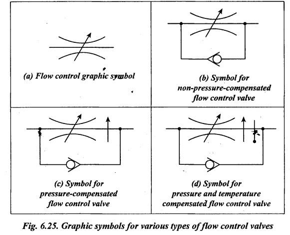
![]() across the orifice symbol represents that the orifice can be adjusted.
across the orifice symbol represents that the orifice can be adjusted.![]() represents temperature compensation.
represents temperature compensation. represents unidirectional flow.
4. Relationship Between Flow Rate and Pressure Drop For a Flow Control Valve
Hydraulics and Pneumatics: Unit II: Hydraulic Actuators and Control Components : Tag: : Hydraulic Actuators and Control Components - Hydraulics and Pneumatics - pressure-compensated flow control valves
Related Topics
Related Subjects

Hydraulics and Pneumatics
ME3492 4th semester Mechanical Dept | 2021 Regulation | 4th Semester Mechanical Dept 2021 Regulation