Engineering Graphics: Unit II (c): Projections of Straight Lines
Positions of a Line in Dihedral Angles
Engineering Graphics (EG)
A line may be positioned in infinite number of positions in Dehedral angles (ie, with respect to the vertical and horizontal reference planes).
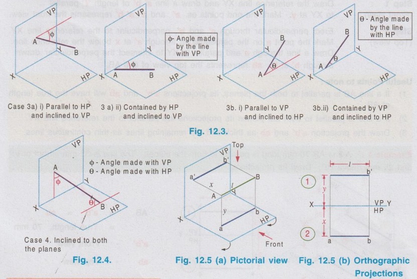
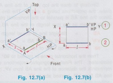
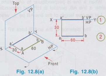
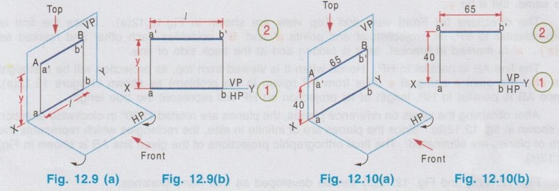
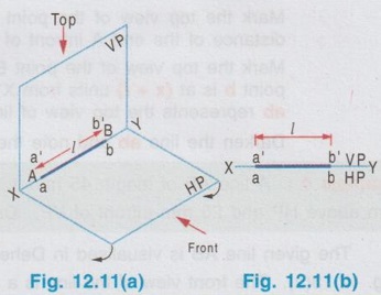
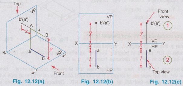
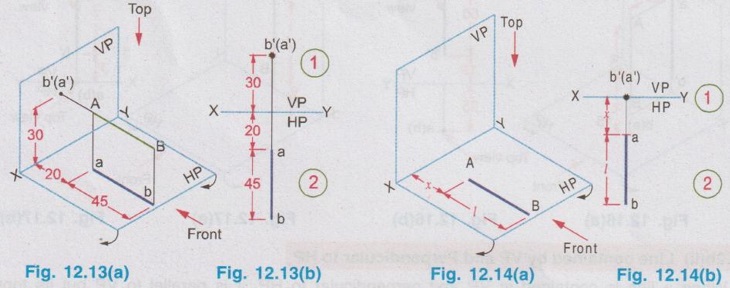
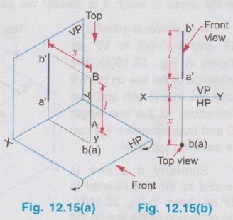
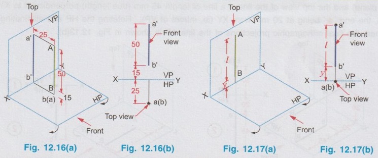
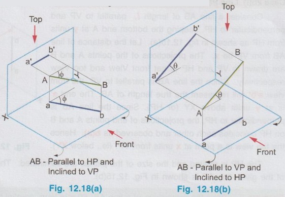
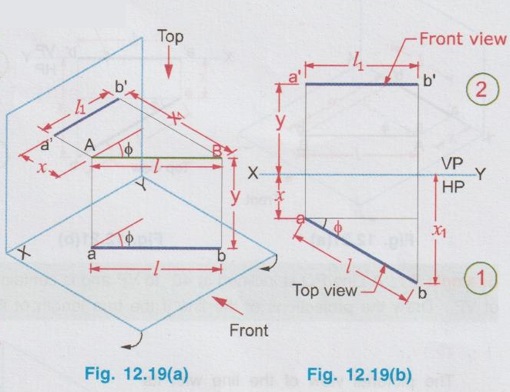
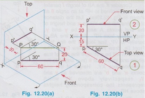
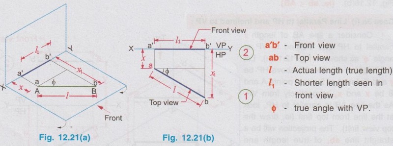
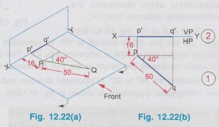
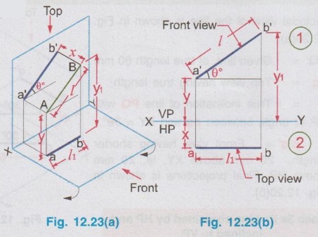
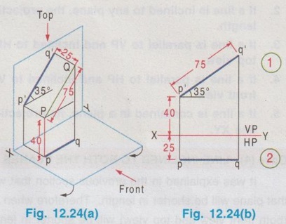
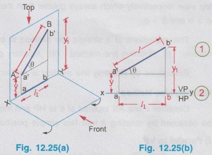
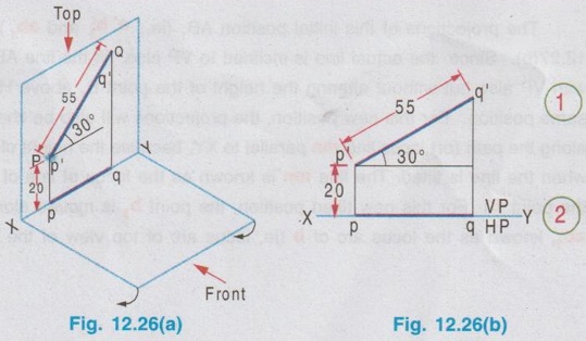
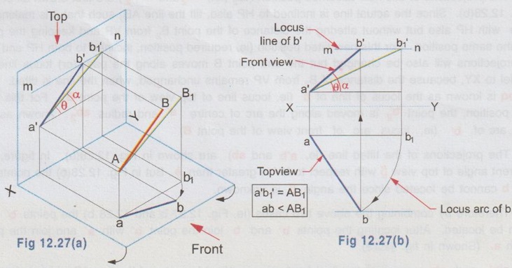
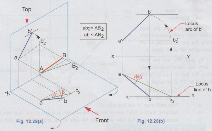
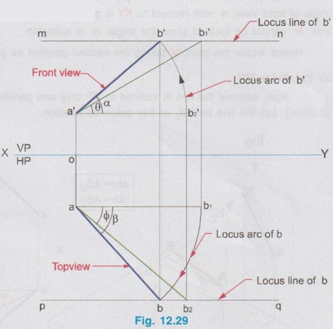
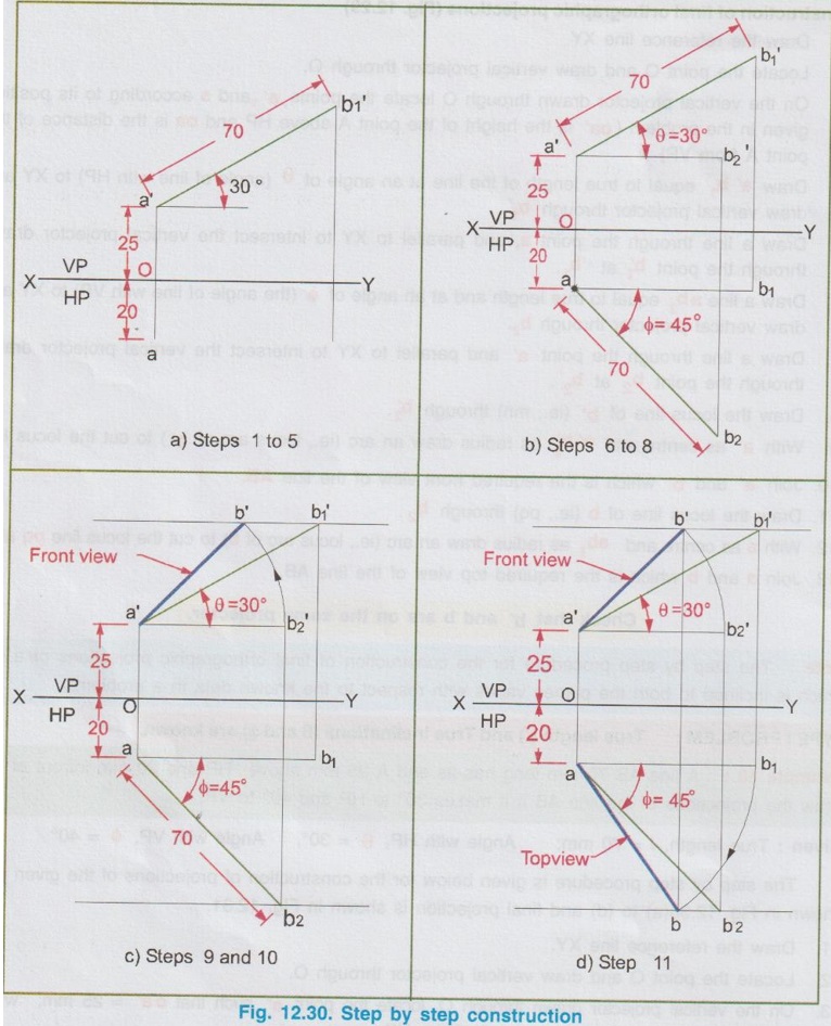
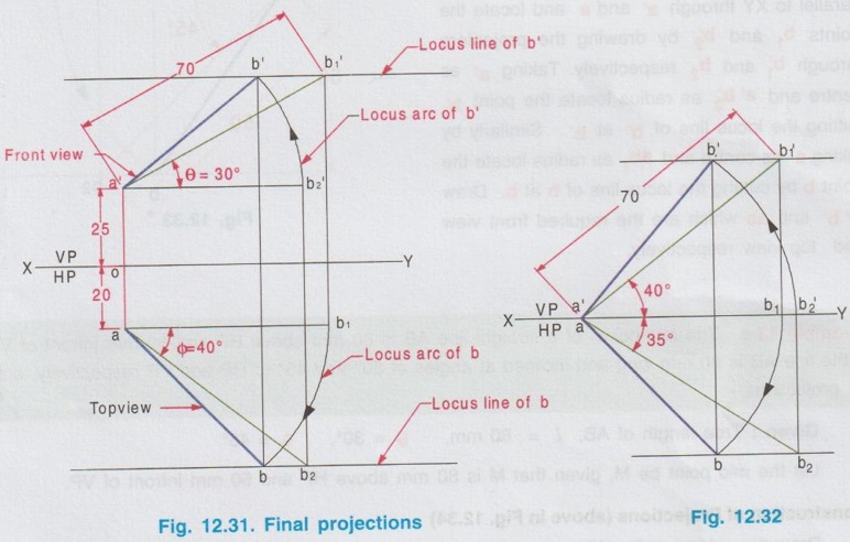
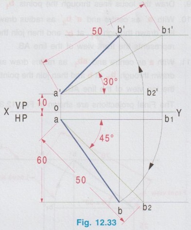
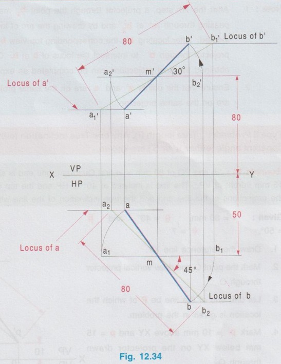
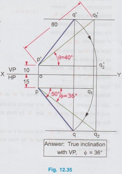
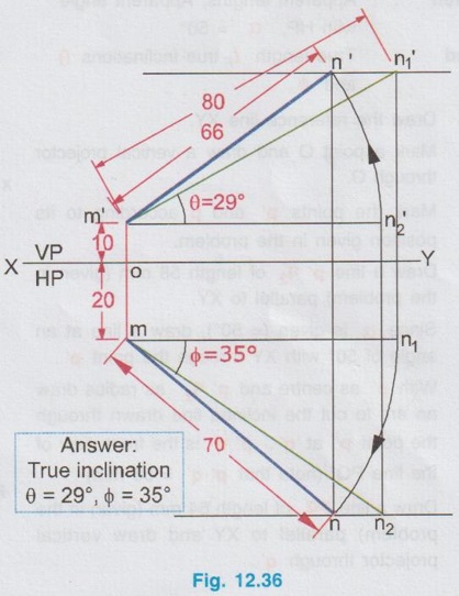
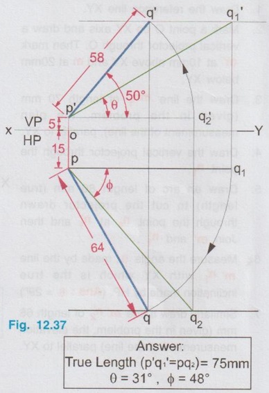
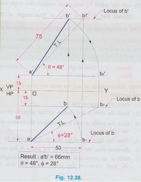
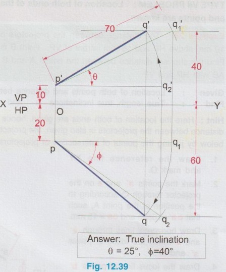
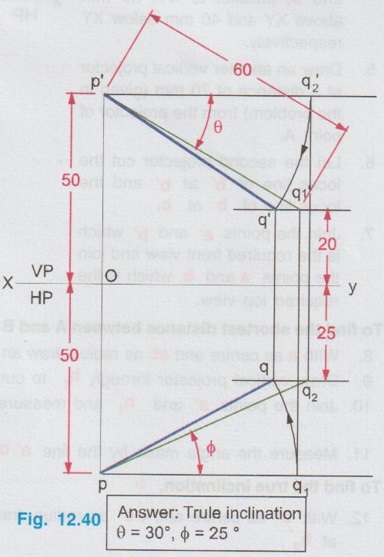
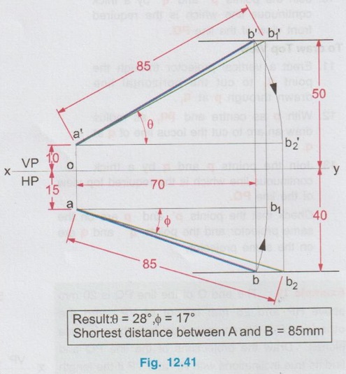
POSITIONS OF A LINE IN DIHEDRAL ANGLES A line may be positioned in infinite number of positions in Dehedral angles (ie, with respect to the vertical and horizontal reference planes). Major positions of line with respect to HP and VP are given below. Fig. 12.5(a) shows the pictorial view of a line AB of length 'l' in first quadrant, parallel to both HP & VP. Let the line AB is at 'x' distance from VP and 'y' height above HP. Since the line AB is parallel to both HP & VP, the distance of the points A and B from VP is the same. Similarly the height of the points A and B from HP is the same. Let the line AB be observed as shown in fig. 12.5(a) for front view and top view. Taking the ends of the line A and B, the projections of these points on vertical plane a' and b' are seen. The line joining these projections is the front view of the line AB. Since the line AB is parallel to VP length of its front view a' b' is equal to the actual length of the line l, known as the True length. Similarly to draw the top view of the line AB, project the end points A and B to the horizontal plane, the projections being a and b. The line joining these points is the top view of the line AB. Since the line AB is parallel to the horizontal plane, length of its top view ab is equal to the actual length, known as the true length of the line AB. AB = Straight line of actual length (or) True length 'l' a'b' = Front view of AB = l (since AB is parallel to VP) ab = Top view of AB = l (since AB is parallel to HP) Then the horizontal plane is rotated to 90° in clockwise direction and the reference planes are eliminated. The Final orthographic projections of the line AB are shown in Fig. 12.5(b) in which x represents the distance of the line AB from VP, marked below XY and y represents the height of the line AB from HP, marked above XY. Note: i) Fig. 12.5(a) can be developed as a free hand sketch and Fig. 12.5(b) to be drawn to scale. ii) To draw the orthographic projections (ie, Fig. 12.5 b), the following steps can be followed. Step 1 : (Front view) Draw the reference line XY and draw a line a' b' of length 'l' parallel to XY at y. Mark the end points as a' and b'. a' b' represents the front view. Step 2 (Top view) Erect perpendicular through a' and b', perpendicular to the reference line XY. Mark the point a on the perpendicular through a' at x below the reference line. Draw a line through a and parallel to XY to intersect the perpendicular drawn through b' at b. ab represents the top view of line AB. Useful Points to note: 1) If a line AB is parallel to both the planes, its projections a'b' and ab will have the true length of AB. 2) If a line is parallel to both the planes its projections are parallel to the reference line XY. 3) Draw the projection a'b' and ab as thick and the remaining lines as thin continuous lines. Example 1: A line AB 70 mm long is parallel to both the planes. The line is 35 mm infront of VP and 25 mm above HP. Draw its projections. The position of line AB in dehedral angles is shown in pictorial view in Fig. 12.6(a). As the line AB is parallel to both the planes, both front view and top view represents the true length of the line. Final projections of line AB is shown in Fig. 12.6(a). Case 1(b) Line contained by HP and Parallel to VP Consider a line AB of length l, contained in HP and parallel to VP, placed at x distance from VP as shown in pictorial view (Fig. 12.7 a). Here the height of AB from HP, y = 0 (since the line is contained by HP). The directions for Front view and top view are X shown in fig. 12.7(a). Front view a'b' coincides on reference axis and the top view ab coincides on AB, at x units from VP, Rotating the HP and eliminating the size of planes, the final projections are obtained as shown in Fig. 12.7(b). Example 2: A line AB, 60 mm long lies in HP and 30 mm infront of VP. Draw its projections. The pictorial view of the line is shown in Fig. 12.8(a). Front view a'b' coincides with XY and the top view ab is parallel to XY, of length equal to 60 mm (true length) and at 30 mm from VP. The final orthographic projections is shown in Fig. 12.8(b). AB = True length, 60 mm a'b' = ab = 60 mm Case 1(c) Line contained by VP and Parallel to HP Consider a line AB of length l, contained by VP and parallel to HP, placed at height y from HP as shown in pictorial view (Fig. 12.9 a). Since the line AB contains in VP, its distance from VP, x = 0. The directions for Front view and Top view are shown in pictorial view. Since the line is contained by VP, its top view ab of length l (True length) coincides on reference axis XY and the front view a'b' coincides on the line AB, at y units above HP. Orthographic projections is obtained as shown in Fig. 12.9(b). Example 3: Draw the projections of a line AB of length 65 mm, lying in VP and 40 mm above HP. Here the line AB lies in VP, ⸫ x = 0 and it is given y = 40 mm. The pictorial view of the line is shown in Fig. 12.10(a). Rotating the plane in clockwise direction and eliminating the size of the planes, the final orthographic projections is shown in Fig. 12.10 (b). Case 1(c) Line contained by Both the planes : Consider a line AB of length l which contains in both HP and VP, ie., coincides with the reference axis XY as shown in Fig. 12.11(a). As the line is on reference axis, the front view a'b' and top view ab coincide with each other and with the given line AB, which lies on the reference axis. The final orthographic projections of the line AB is shown in Fig. 12.11 (b). To draw the projections shown in Fig. 12.11 (b), draw the reference axis XY and mark the point a' (also a) and mark the point b' (also b) at l from the point a'. Case 2a(i) Line Parallel to HP and Perpendicular to VP. When a line is perpendicular to one plane it will be automatically parallel to the other plane. Consider a line AB, parallel to HP and perpendicular to VP as shown in Fig. 12.12(a). Let the true length of the line AB be l, which is perpendicular to VP, being the end A at x units from VP. ⸫ The distance of the end B from VP = (x + l) It is given that the line is parallel to HP. Hence height of end points A and B from HP will be the same. Let it be y. The directions for Front view and Top view are shown in Fig.12.12(a). Since the line is perpendicular to VP, its projection of end points a' and b' coincides each other and marked as b'(a'). a' is marked in bracket, as it is hidden and at the back side of line. The line AB is parallel to HP. Hence when it is viewed from top, its projection will be a straight line ab, the point a being at x units from VP (given in the problem) as shown in figure 12.12(a). Since AB is parallel to HP, length of its projection on HP will represent the true length. After obtaining the views on reference planes, the planes are rotated to 90° in clockwise direction as shown in fig. 12.12(b). Since the planes are of infinite in size, the rectangles which represents the size of planes are eliminated. The final orthographic projections of the given line AB is shown in Fig. 12.12(c). Fig. 12.12(a) and Fig. 12.12(b) can be developed as free hand sketches. To draw the Final Projections (Fig. 12.12 c) Step 1: Draw the reference line XY. Locate the Front view b'(a') as a thick point at a height of y units above XY which represents the height of the line AB above HP. Step 2: Draw the projector of front view, which is perpendicular to the reference line. Mark the top view of the point A as a, at x units below XY, which represents the distance of the end A infront of VP (given in the problem). Mark the top view of the point B as b, at l (true length) distance from a such that the point b is at (x + l) units from XY, which represents the distance of the end B from VP. ab represents the top view of line AB. Darken the line ab and note the given dimensions as shown in Figure. Example 4: A line AB of length 45 mm is parallel to HP and perpendicular to VP. Point A is 30 mm above HP and 20 mm infront of VP. Draw its projections. The given line AB is visualised in Dehedral angles and its pictorial view is drawn as shown in Fig. 12.13(a). The front view of the line is a point b'(a') seen on VP at 30 mm above XY (ie, above 12.7 HP plane) and the top view of the line is a line of length 45 mm (true length) perpendicular to XY (or VP), the end a being at 20 mm from XY (ie, infront of VP). Rotating the HP and eliminating the planes, the final orthographic projections of the line AB is shown in Fig. 12.13(b). Case 2a(ii) Line contained by HP and Perpendicular to VP When a line is contained by HP and perpendicular to VP, it is parallel to HP but its front view coincides with the reference axis XY. A line AB, contained by HP and perpendicular to VP is shown above in Fig. 12.14(a) and its orthographic projections are shown above in Fig. 12.14(b). Case 2b(1) Line Parallel to VP and Perpendicular to HP Consider a line AB of length l, parallel to VP and perpendicular to HP, keeping the bottom end A at y units from HP as shown in fig. 12.15(a). Let the distance of line AB from VP be x. The projections of the points A and B are drawn to VP and HP to get front View and top View respectively. Since the line AB is parallel to VP, the front view a'b' will represent the true length of AB. The end a' is at y units above XY (or HP). Since the line AB is perpendicular to HP, the projections of end points A and B on HP coincides each other and observed as b(a). Hence the top view is a point at x units from VP. (ie., below XY). The HP is rotated and the size of the planes are eliminated. The final orthographic projections of the given line AB is shown in Fig. 12.15(b). Example 5: Draw the projections of a line AB, 50 mm long, parallel to VP and perpendicular to HP. Point A is 65 mm above HP and 25 mm infront of VP. Point B is 15 mm above HP and 25 mm infront of VP. Pictorial view of the line in dihedral angles is shown in Fig. 12.16(a). Front view of the line a'b' of length equal to 50 mm (true length) is seen on VP, the bottom end b' being at 15 mm above HP. The top view of the line is seen as a point a(b), at a distance of 25 mm from VP. Rotating the HP and neglecting the size of reference planes, Final orthographic projections of the given line are drawn as shown in Fig. 12.16(b). Case 2b(ii) Line contained by VP and Perpendicular to HP When a line is contained in VP and perpendicular to HP, it is parallel to VP but its topview coincides with the reference axis XY. Pictorial view of a line AB, contained in VP and perpendicular to HP is shown above in Fig. 12.17(a) and its orthographic projections are shown above in Fig. 12.17(b). Case 3: LINE PARALLEL TO ONE PLANE AND INCLINED TO OTHER PLANE When a line is parallel to one of the reference planes and inclined to other plane, its projection on the plane to which it is parallel will have the true length and true inclination. ie, If a line is parallel to HP and inclined to VP as shown in Fig. 12.18(a), the projection of the line on HP will have the true length and true inclination. ie, the true length (l) and true inclination (ϕ) can be seen on top view. Similarly if a line is parallel to VP and inclined to HP as shown in Fig. 12.18(b), the projection of the line on the VP will have the true lengths and true inclination. ie, the true length (l) and true inclination (θ) can be seen on front view. It is also interesting to note that if a line is inclined to any plane the projection of line on that plane is a straight line having shorter length and parallel to XY line. ie, if a line is inclined to VP, the projection of the line on VP (ie, Front View) is a straight line having shorter length than the actual length and parallel to the reference axis XY as shown in Fig. 12.18(a). (ie, a'b' < AB) Similarly if a line is inclined to HP, the projection of the line on HP (ie, top view) is a straight line having shorter length than the actual length and parallel to the reference axis XY as shown in Fig. 12.18(b). (ie, ab < AB). Case 3a (i) Line Parallel to HP and Inclined to VP : Consider a line AB of length l parallel to HP and inclined to VP at angle 'ϕ' as shown in Fig. 12.19(a). Let the height of the line AB above HP be y and distance of the end points A and B be x and x1 respectively from VP. As the line AB is parallel to HP, look at the line from top first (ie, draw the top view first). The projection will be a straight line ab, of true length and inclined at an angle ϕ to the reference axis XY. Distance of the end points from XY are observed as x and x1 respectively which represents the corresponding distances from VP. Then look at the line AB for front view. As the line AB is inclined to VP, its projection on VP is a straight line of apparent length (shorter length) and parallel to reference axis XY. This projection a'b' is the front view, y units above XY which represents the height of the line AB above HP. Rotating the HP to 90° in clockwise direction and eliminating the size of reference planes the final orthographic projections is shown in fig. 12.19(b). Example 6: A line PQ 60 mm long is parallel to HP and inclined at an angle of 30° to VP. The point P is 20 mm above HP and 15 mm infront of VP. Draw its projections. Pictorial view of the line is shown in Fig. 12.20(a). PQ = Given line, of true length 60 mm pq = Top view having true length ϕ = True inclination of line PQ with VP or angle between pq and XY = 30°. p'q' = Front view having shorter length, 20 mm above XY, ie, 20 mm above HP. Final projections is shown in Fig. 12.20(b). Case 3a ii) Line contained by HP and inclined to VP A line contained by HP means it is parallel to HP. So this case is similar to the previous case 3a i) but the height of the line above HP, ie, y is zero. Hence the pictorial view and orthographic projections are developed as the previous case taking the value of y = 0, as shown in Fig. 12.21(a) and 12.21(b) respectively (when y = 0, Front view coincides with XY and top view coincides with the actual line) Example 7: A Line PQ is inclined at 40° to VP and is contained by HP. The end P is 16 mm infront of VP. Draw the projections of the line if the true length of line PQ is 50 mm. The pictorial view of the line with its projections and the final orthographic projections are shown in Figures 12.22(a) and 12.22(b) respectively. Case 3b (1) Line Parallel to VP and inclined to HP. Consider a line AB of length l parallel to VP and inclined to HP at an angle θ as shown in Fig. 12.23(a). Let the distance of the line AB from VP be x and height of the end points A and B be y and y1 respectively from HP. As the line AB is parallel to VP, first look at the line from Front (ie, draw the front view first). The projection will be a straight line a'b' of true length and inclined at θ (true angle) to the reference axis XY. Height of the end points a' and b' are observed as y and y1 respectively above XY which represents the corresponding heights above HP. Then look at the line AB for Top view. As the line AB is inclined to HP, its projection on HP is a straight line of shorter length and parallel to the reference axis XY. This projection ab is the top view, x units from XY which represents the distance of the line AB from VP. Final orthographic projections of the line is shown in fig. 12.23(b). Example 8: A line PQ 75 mm long is parallel to VP and inclined at 35° to HP. If the end P is 40 mm above HP and 25 mm infront of VP, draw the projections of the line PQ. Pictorial view of the line with its projections is shown in Fig. 12.24(a). Since the line PQ is parallel to VP, the projection on VP ie, front view will show the true length of the line and true angle of inclination with HP. Since the line PQ is inclined to HP, its projection on HP, ie top view is a straight line having shorter length. Hence, draw the front view first and then draw the top view. The final projections of the line is shown in Fig. 12.24 (b). Case 3b (ii) Line contained by VP and inclined to HP. A line contained by VP means it is parallel to VP. So this case is similar to the previous case 3b i) but the distance of the line infront of VP, ie, x is zero. Hence the pictorial view and orthographic projections are developed as the previous case taking the value of x = 0 as shown in Fig. 12.25(a) and Fig. 12.25(b) respectively. (When x = 0, top view coincides with reference axis XY and front view coincides with the actual line). Example 9: Draw the projections of a line PQ, inclined at 30° to HP and contained by VP. The end P is 20 mm above HP. If the true length of the line PQ is 55 mm draw its projections. The pictorial view of the line with its projections and the final orthographic projections are shown in figures 12.26(a) and 12.26(b) respectively. Useful points to note: 1. If a line is parallel to any plane, the projection on that plane will have the true length and true inclination. 2. If a line is inclined to any plane, the projection on that plane will have a reduced apparent length. 3. If a line is parallel to VP and inclined to HP, draw the front view first and then draw the sanil edito top view. 4. If a line is parallel to HP and inclined to VP, draw the top view first and then draw the front view. 5. If a line is contained in a plane, its projection on the other plane will be on the reference line XY. Case (4) LINE INCLINED TO BOTH THE PLANES It was explained in the previous section that when a line is inclined to a plane, its projection on that plane will be shorter in length. Therefore when a line is inclined to both HP and VP its projections (both front view and top view) will be shorter in length and make angles a and ẞ with reference line XY. (a with HP and ẞ with VP). a and ẞ are known as apparent angles observed in front view and top view respectively which always greater than the true inclination with HP and VP respectively.(ie., α > θ and β > ϕ). The projections of a straight line inclined to both the planes can be obtained by two methods namely (i) Rotating line method (ii) Auxiliary plane (or) Trapezoidal method. Projections by Rotating line method is explained below. Rotating Line Method : Consider a line AB inclined at 0 to HP and inclined at to VP. The projections of this line can be obtained by rotating it into two simple positions as i) Parallel to VP and ii) Parallel to HP. i) Parallel to VP Though the line is inclined to both the planes let us assume initially the line is inclined to HP only at 9 and parallel to VP [ [case 3b(i)] as shown in Fig. 12.27(a)]. Let the line be AB, at this initial position. The projections of this initial position AB, (ie., a' b1' and ab1) are first drawn as shown in Fig. 12.27(b). Since the actual line is inclined to VP also, tilt the line AB, such that it is making an angle with VP also but without altering the height of the point B, above HP and keeping the point A at the same position. For this new position, the projections will also be changed but the end point B, moves along the path (or) locus line mn parallel to XY, because the height of B, above HP remains unchanged when the line is tilted. The line mn is known as the locus of line of b'. (ie, locus line of front view of the point B) For this new tilted position, the point b1 is moved along the arc of centre a and radius ab1, known as the locus arc of b (ie, locus arc of top view of the point A). The projections of the tilted line (ie, a'b' and ab) are shown in Fig. 12.27(b). The apparent angle of front view α with respect to XY is greater than θ. But in the figure 12.27(b) the points b' and b cannot be located since the angle α is unknown. Hence locate the point b' taking the second position as parallel to HP. ii) Parallel to HP Now, assume the line is inclined to VP only and parallel to HP [case 3a(i) as shown in Fig. 12.28(a)] Let the line be AB2 at this assumed position. The projections of this new assumed position AB2 (ie., ab2 and a' b'2) are first drawn as shown in fig. 12.28(b). Since the actual line is inclined to HP also, tilt the line AB2 such that it is making an angle with HP also but without altering the distance of the point B2 from VP and keeping the point A at the same position. For this new tilted position (ie, required position, inclined to both HP and VP) the projections will also be changed but the end point B moves along the path (or) locus line pq parallel to XY, because the distance of B2 from VP remains unchanged, when the line is tilted. The line pq is known as the locus of line of b (ie, locus line of top view of the point B). tilted position, the point b2' is moved along the arc of centre a' and radius ab'2, locus arc of b' (ie, locus arc of front view of the point B) The projections of the tilted line (ie, a'b and ab) are shown in Fig. 12.28(b). In figure, the apparent angle of top view β with respect to XY is greater than ϕ. But in Fig. 12.28(b) the points b' and b cannot be located since the angle β is unknown. Therefore by combining the above two cases (ie, Fig. 12.27 b and 12.28 b) the points b' and b can be located. After locating the points b' and b join the point b' with a' and join the point b with a. (Shown in fig. 12.29). a'b' and ab represents the final front view and final top view of the line AB which is inclined at θ to HP and ϕ to VP. Notations used and general construction procedure The final projections of a line which is inclined to both the planes with various notations are shown in fig. 12.29. Let the line be AB inclined to both the planes. a'b' - Front view ab - Top view a' b'1 and ab1 are the front view and top view respectively assuming the line is parallel to VP and inclined to HP at an angle θ. a' b'2 and ab2 are the front view and top view respectively assuming the line is parallel to HP and inclined to VP at an angle θ. Hence, θ - True inclination of the line with HP & ϕ - True inclination of the line with VP. α - Apparent angle of front view of the line AB with HP. ie.,angle of a'b' line with XY. β - Apparent angle of top view of the line AB with VP. ie.,angle of ab line with XY. Note that a' b'1 = ab2 = True length, l. Construction of final orthographic projections (Fig. 12.29) 1. Draw the reference line XY. 2. Locate the point O and draw vertical projector through O. 3. On the vertical projector drawn through O locate the points a' and a according to its position given in the problem (oa' is the height of the point A above HP and oa is the distance of the point A from VP) 4. Draw a' b'1 equal to true length of the line at an angle of θ (angle of line with HP) to XY and draw vertical projector through b'1. 5. Draw a line through the point a, and parallel to XY to intersect the vertical projector drawn through the point b1' at b1. 6. Draw a line ab2 equal to true length and at an angle of ϕ (the angle of line with VP) to XY and draw vertical projector through b2. 7. Draw a line through the point a' and parallel to XY to intersect the vertical projector drawn through the point b2 at b2'. 8. Draw the locus line of b' (ie., mn) through b1'. 9. With a' as centre and a' b2' as radius draw an arc (ie., locus arc of b') to cut the locus line mn at b'. 10. Join a' and b' which is the required front view of the line AB. 11. Draw the locus line of b (ie., pq) through b2. 12. With a as centre and ab1 as radius draw an arc (ie., locus arc of b) to cut the locus line pq at b. 13. Join a and b which is the required top view of the line AB. Check that b' and b are on the same projector. Note: The step by step procedure for the construction of final orthographic projections of a line which is inclined to both the planes varies with respect to the known data in a problem. TYPE I PROBLEM: True length (l) and True inclinations (θ and ϕ) are known. Example 10: A line AB 70 mm long has its end A 25 mm above HP and 20 mm infront of VP. Draw the projections of the line AB if it makes 30° to HP and 40° to VP. Given True length, l = 70 mm; Angle with HP, θ = 30°, Angle with VP, ϕ = 40° The step by step procedure is given below for the construction of projections of the given line, shown in Fig. 12.30(a) to (d) and final projection is shown in Fig. 12.31. 1. Draw the reference line XY. 2. Locate the point O and draw vertical projector through O. 3. On the vertical projector drawn through O, locate the point a' such that oa' = 25 mm, which represents the height of the point A above HP. 4. On the vertical projector drawn through O, locate the point a below XY such that oa = which represents the distance of the point A infront of VP. 5. Draw a line a' b1' equal to true length of the line (70mm) at 30° (θ) to the reference line XY, which represents the true inclination of the line AB with HP and draw vertical projector through b1'. 6. Draw a line through the point a and parallel to XY to intersect the vertical projector drawn through the point b1' at b1. 7. Draw a line ab2 equal to true length of the line (70 mm) and at 40° (ϕ) to the reference line XY, which represents the true inclination of the line AB with VP and draw vertical projector, through b2 upward. 8. Draw a line through the point a' and parallel to XY to intersect the vertical projector drawn through the point b2 at b2'. 9. Draw the locus lines through the points b1' and b2 respectively which are parallel to XY. 10. With a' as centre and a' b2' as radius draw an arc (ie, locus arc of b') to intersect the locus line drawn through b1' at b' and then join the points a' and b' by thick continuous line, which represents the front view of the line AB. 11. With a as centre and ab1, as radius draw an arc (ie, locus arc of b) to intersect the locus line drawn through b2 at b and then join the points a and b by thick continuous line, which represents the top view of the line AB. The Final projections are shown in Fig. 12.31. Note: Check that the points b' and b are on the same vertical projector. Example 11: A line AB of length 70 mm is inclined at 40° to HP and 35° to VP. If the end A is in both HP and VP, draw its projections. Hint: The end A is in both HP and VP. ie, the point A lies on reference axis. Hence the procedure explained in example 10 can be followed, but locating a' and a (which coincides each other) on reference axis. The projections of line AB are shown above in Fig. 12.32. Example 12: A straight line AB of 50 mm long has its end A 10 mm above HP and the end B 50 mm infront of VP. Draw the projections of line AB if it is inclined at 30° to HP and 45° to VP. The projections are shown in Fig. 12.33. Hint: Draw XY line. Locate a', 10mm above XY. Draw a' b'1 of length 50 mm and at an angle 30°. Draw locus line of b 60 mm below XY. Draw the vertical projector through a'. Locate the points a and b2 such that the line ab2 is making an angle of 45° cutting the vertical projector drawn through a' at a and locus line of b at b2, equal to 50 mm length. Draw the lines parallel to XY through a' and a and locate the points b1 and b'2 by drawing the projectors through b'1 and b2 respectively. Taking a' as centre and a' b'2 as radius locate the point b' cutting the locus line of b' at b'. Similarly by taking a as centre and ab1 as radius locate the point b by cutting the locus line of b at b. Draw a' b' and ab which are the required front view and top view respectively. Example 13: The mid-point of a straight line AB is 80 mm above HP and 50 mm infront of VP. If the line AB is 80 mm long and inclined at angles of 30° and 45° to HP and VP respectively, draw its projections. Given : True length of AB, l = 80 mm, θ = 30°, ϕ = 45° Let the mid point be M, given that M is 80 mm above HP and 50 mm infront of VP. Construction of Projections (above in Fig. 12.34) 1. Draw the reference line XY. 2. Draw a line parallel to XY and above XY at a distance of 80 mm and mark a point m' on it which represents height of mid point above HP. 3. Draw the vertical projector through the point m' and mark the point m 50 mm below XY which represents the distance of the mid point infront of VP. Also draw the horizontal line through m. 4. Draw a line of length 80 mm (true length) through the point m' at an angle of 30° (θ) to XY and mark the end points as a1' and b1' (ensure that a a1' m' = m' b1' = = 1/2 × true length). 5. Through the points a1' and b1' draw horizontal lines parallel to XY which are the locus of the points a' and b' respectively. 6. Draw a line of length 80 mm (true length) through the point m at an angle of 45° (ϕ) to XY and mark the end points as a2 and b2. (ensure that a2m = mb2 = 1/2 × true length) 7. Through the points a2 and b2 draw horizontal lines parallel to XY which are the locus of the points a and b respectively. 8. Through the point b1' draw vertical projector to cut the horizontal line drawn through the point m at b1. Clearly mb1 represents the corresponding top view of front view m' b1'. 9. Now with m as centre mb1 as radius draw an arc to cut the locus of b (ie., drawn through b2) at b. 10. Draw the vertical projector through the point b to cut the locus of b' at b'. 11. Join the points b and m and extend it to cut the locus of a (ie., drawn through a2) at a and then join the points a and b by thick continuous line, which is the required top view of the given line. 12. Join the points b' and m' and extend it to cut the locus of a' (ie., drawn through a2) at a and then join the points b' and a' by thick continuous line, which is the required front view of the given line. Note: 1. After the 7th step, a projector through the point b2 may also be drawn to cut the line passing through m' at b'2 and by drawing the arc of locus of b'2, the point b' may be located. After locating b', the corresponding top view b can be obtained by drawing the projector through b' to intersect the locus of b at b. Once the points b' and b are obtained the final projections can be completed as explained in step 11 and 12. 2. Ensure that the points a' and a are on the same projector and the points b' and b are on the same projector. Type II Problem: True length (l), Any one True inclination (either θ or ϕ) and any one apparent angle (either α or β) are known. Example 14: A line PQ of 80 mm is in first Quadrant, one end is situated at 10 mm above HP and 15 mm infront of VP. The line is inclined at 40° to HP and the top view makes 50° with VP. Draw line and find the true inclination of the line with VP. Given: l = 80 mm, θ = 40° and β = 50°, ϕ = ? 1. Draw the reference line XY. 2. Mark the point O and draw vertical projector through O. 3. Let one end of the line be P of which the location is given in the problem. 4. Mark p' = 10 mm above XY and p = 15mm below XY on the projector drawn through O. 5. Draw horizontal lines through p' and p, parallel to XY line. 6. Draw line p'q'1 of length 80 mm (true length) at an angle of 40° (θ) to XY. 7. Draw vertical projector through q'1 to cut the inclined line drawn through p at q1. 8. Draw a line at an angle of 50° (β) to XY. Draw an arc with p as centre and pq1 as radius to cut the inclined line drawn through p at q and draw horizontal line through q, which represents the locus line of q. 9. Draw the locus line of q' through q'1 which is parallel to XY. 10. Draw the vertical projector through the point q to cut the locus line of q' and then join the points p' and q' which is the required front view of the line. 11. Now with p' as centre and p' q' as radius draw an arc to cut the horizontal line drawn through p' at q'2. 12. Draw vertical projector through the point q'2 to cut the locus line of q at q2. 13. Join the points p and q2 and measure the angle made by the line pq2with XY, which is the true inclination of the line with V.P. (ϕ). By measuring ϕ = 36°. pq and p' q' represents top view and front view respectively. Note: If the apparent angle made by the line with HP (ie, α) is required, measure the angle made by the line p'q' with XY. Type III Problem: True length (l) and apparent lengths (both in front view and top view) are known. Example 15: Draw the projections of a line MN of 80 mm long if its elevation and plan measures 66 mm and 70 mm respectively. The end M is at 10 mm above HP and 20 mm infront of VP. Given: l = 80 mm and apparent lengths; θ = ? ϕ = ? 1. Draw the reference line XY. 2. Mark a point O on XY axis and draw a vertical projector through O. Then mark m' at 10mm above XY and m at 20mm below XY. 3. Draw the line mn1 of length 70 mm (given in the problem, the plan measurement of the line), parallel to XY. 4. Draw the vertical projector through the point n1. 5. Draw an arc of length 80 mm (true HP length) to cut the projector drawn through the point n1 at n1' and then Join m' and n'1. 6. Measure the angle θ, made by the line m'n1' with XY which is the true inclination made by HP. (Ans: θ = 29°) 7. Similarly draw a line m' n'2 of length 66 mm (given in the problem, the elevation measurement of the line) parallel to XY. 8. Draw the vertical projector through the point n'2 below XY. 9. Draw an arc of length 80 mm (l) to cut the projector drawn through the point n'2 at n2 and then join the points m and n2. 10. Measure the angle ϕ made by the line mn2 with XY which is the true inclination made by VP. To draw Front view 11. Draw the locus line through not tub of n'1. 12. With m' as centre and mn'2 as radius draw an arc to cut the locus line drawn through n'1 at n'. 13. Join the points m' and n' by thick continuous line which is the required front view (note that m' n' = m' n'2 = 66 mm) To draw Top View 14. Draw the locus line through n2. 15. With m as centre and mn1 as radius draw an arc to cut the locus line drawn through n2 at n. 16. Join the points m and n by thick continuous line which is the required top view (note that mn1 = mn = 70 mm) Type IV Problem: Apparent lengths (both in front view and top view) and any one apparent angle (either α or β) are known. Example 16: One end of a line PQ is at 5 mm above HP and 15 mm infront of VP. If its elevation and plan measures 58 mm and 64 mm respectively and the elevation is inclined at 50°, draw the projections of the line and find the true length and true inclinations of the line. Given : Apparent lengths, Apparent angle with HP, α = 50° Find: True length l, true inclinations θ and ϕ. 1. Draw the reference line XY. 2. Mark a point O and draw a vertical projector through O. 3. Mark the points p' and p according to its position given in the problem. 4. Draw a line p' q'2 of length 58 mm (given in the problem) parallel to XY. 5. Since α is given (= 50°), draw a line at an angle of 50° with XY through the point p'. 6. With p' as centre and p' q'2 as radius draw an arc to cut the inclined line drawn through the point p' at q'. p' q' is the front view of the line PQ. (note that p' q' = 58 mm) 7. Draw a line pq1 of length 64 mm (given in the problem) parallel to XY and draw vertical projector through q'. 8. With p as centre and pq1 as radius draw an arc to cut the vertical projector drawn through the bhs point q' at q. 9. Join the points p and q which is the top view of the line PQ (note that pq = 64 mm) To find True Inclination θ and true length l 10. Draw the locus line through the point q' and draw a vertical projector through q1 to cut the locus line at q1'. 11. Join the points p' and q1' and measure its length which is the true length of the line. (Ans: l = 75 mm). 12. The angle made by the line p' q1' with XY is the true inclination with HP. (Ans: θ = 31°) To find True inclination ϕ 13. Draw the locus line through the point q2 and draw a vertical projector through the point q'2 to cut the locus line at q2. 14. Join the points p and q2 and measure the angle ϕ made by the line pq2 with XY, which is the true inclination of the line with VP. (Ans: ϕ = 48°) TYPE V PROBLEM: True length (l) and any one apparent length (either in front view or top view) are known. Example 17: End A of the line AB of 75 mm long is 50 mm infront of VP and 15 mm above HP. End B is 15 mm infront of VP and above HP. Top view of the line is measured to be 50 mm long. Determine the front view length and the true inclination. Given : l = 75 mm, Apparent length in top view 50 mm. Find : Apparent length in front of view, true inclinations θ and ϕ. 1. Draw the reference line XY and mark a point O. 2. Draw a vertical projector through the point O and Mark the points a' and a according to the position of the point A given in the problem. (oa' = 15mm; oa = 50 mm). 3. Point B is 15 mm infront of VP. Hence draw the locus of the point b as a straight line, 15 mm below XY and parallel to XY. 4. Length of line in top view is given as 50 mm. Hence take the point a as centre and radius equal to 50 mm draw an arc to cut the locus of the point b at b. Then join the points a and b which is the top view of the line AB. 5. Draw a horizontal line through the point a and draw an arc of radius equal to ab with a as centre to cut the line at b1. 6. Draw a vertical projector through the point b1 above XY. 7. With a' as centre and radius equal to 75 mm (true length) draw an arc to cut the projector drawn through the point b1 at b1'. 8. Draw locus of point b' as a straight line passing through b'1 and parallel to XY. 9. Draw a vertical projector through the point b to cut the locus of b' at b' and then join the points a' and b', which is the front view of the line AB and measure its length. (Ans: a' b' = 66 mm) To find true inclination θ 10. Join the points a' and b'1 and measure the angle made by this line with XY. (Ans: θ = 48°) To find true inclination ϕ 11. Taking a' as centre and a' b' as radius draw an arc to cut the horizontal line drawn through the point a' at b'2. 12. Erect vertical projector through the point b'2 to cut the locus of b at b2. 13. Join the points b2 and a and measure the angle made by this line to XY. (Ans: ϕ = 28°) (Check that a' b'1 = ab2 = True length = 75 mm) TYPE VI PROBLEM: True length (l) and position of both ends of the line are known. Example 18: Draw the projections and determine the true inclinations of a straight line of 70 mm long, one end is at 10 mm above HP and 20 mm infront of VP and the other end is at 40 mm above HP and 60 mm infront of VP. Given : True length, l = 70 mm; Locations of both ends Find : θ and ϕ. Hint: Since location of both the ends are given draw the locus of end points in VP and HP first and then proceed. 1. Draw the reference line XY. 2. Mark the point O and draw a vertical projector through O. 3. Mark the points p' and p according to the location of the point P, such that op' = 10 mm and op = 20 mm. 4. Draw the locus line of the end q' in front view 40 mm above XY. 5. Similarly draw the locus line of the end q in top view 60 mm below XY. 6. With p' as centre and 70 mm as radius (true length) draw an arc to cut the locus line of q' at q'1 and measure the angle made by this line with XY for true inclination θ (Ans: θ = 0 25°) 7. Similarly with p as centre and 70 mm as radius (true length) draw an arc to cut the locus line of q at q2 and measure the angle made by this line with XY for true inclination. ϕ (Ans : ϕ = 40°) To draw Front View 8. Draw vertical projector through q2 to cut the horizontal line drawn through p' at q'2. 9. With p' as centre and p' q'2 as radius draw an arc to cut the locus of q' at q'. 10. Join the points p' and q' by a thick continuous line which is the required front view of the line PQ. To draw Top View 11. Erect a vertical projector through the point q q'1 to cut the horizontal line drawn through p at q1. 12. With p as centre and pq1 as radius draw an arc to cut the locus line of q at q. 13. Join the points p and q by a thick continuous line which is the required top view of the line PQ. Check that the points p' and p are on the same projector and the points q' and q are on the same projector. Example 19: The end Q of the line PQ is 20 mm above HP and 25 mm infront of VP and the other end P is 50 mm away from both the reference planes. Draw the projections of the line PQ and find its true inclinations with HP and VP if the length of the line is 60 mm. Given: True length, l = 60 mm and location of both ends Find : θ and ϕ Hint: This is similar to the previous problem. Hence draw the locus of end points first and proceed. The solution is given in Fig. 12.40. Ans: True inclinations, θ = 30° and ϕ = 25°. TYPE VII PROBLEM: Location of both ends of the line and distance between projectors of end points are known. Example 20: The distance between the projectors of two points A and B is 70 mm. Point A is 10 mm above HP and 15 mm infront of VP. Point B is 50 mm above HP and 40 mm infront of VP. Find the shortest distance between the points A and B and measure the true inclinations of the line AB with HP and VP. Given : Location of both points and distance between projectors of end points. Find : True length, true inclinations θ and ϕ Hint: Here the location of both ends are given, hence locus of points can be drawn first. Since the distance between the projectors is also given, the projections of line can be drawn directly as explained below by joining the points of intersection of projectors and locus line of end points. 1. Draw the reference line XY and mark O. 2. Mark the points a' and a on the projector through O according to the position of the point A, such that oa' =10mm and oa = 15 mm. 3. Draw horizontal lines through a' and a which are locus of points a' and a. 4. Draw the locus line of points b' and b, parallel to XY, 50 mm above XY and 40 mm below XY respectively. 5. Draw an another vertical projector at a distance of 70 mm (given in the problem) from the projector of point A. 6. Let the second projector cut the locus line of b' at b' and the locus line of b at b. 7. Join the points a' and b' which is the required front view and join the points a and b which is the required top view. To find the shortest distance between A and B (ie, True length) and true inclination θ 8. With a as centre and ab as radius draw an arc to cut the horizontal line drawn through a at b1'. 9. Draw vertical projector through b1 to cut the locus line of b' at b1'. 10. Join the points a' and b1' and measure which is the true length. (Ans: True length, l = 85 mm) (Ans: θ = 28°) 11. Measure the angle made by the line a' b1' with XY. To find the true inclination, ϕ 12. With a' as centre and ab' as radius draw an arc to cut the horizontal line drawn through a' at b2'. 13. Draw vertical projector through b2' to cut the locus line of b at b2. 14. Join the points a and b2 and measure the angle made by this line with XY. (Ans : ϕ = 17°) Check that a' b1' = ab2 = True length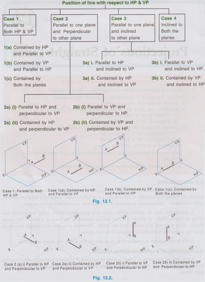
 Case 1(a): Parallel to Both HP & VP
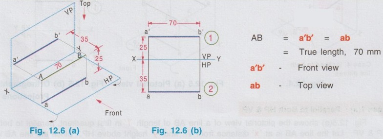
Engineering Graphics: Unit II (c): Projections of Straight Lines : Tag: : Engineering Graphics (EG) - Positions of a Line in Dihedral Angles
Related Topics
Related Subjects

Engineering Graphics
GE3251 eg 2nd semester | 2021 Regulation | 2nd Semester Common to all Dept 2021 Regulation