Hydraulics and Pneumatics: Unit II: Hydraulic Actuators and Control Components
position valves
Introduction, Valve Position
The function of the position valve is to control the introduction of fluid to the lines of the system.
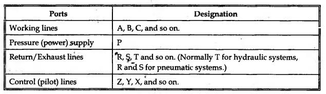
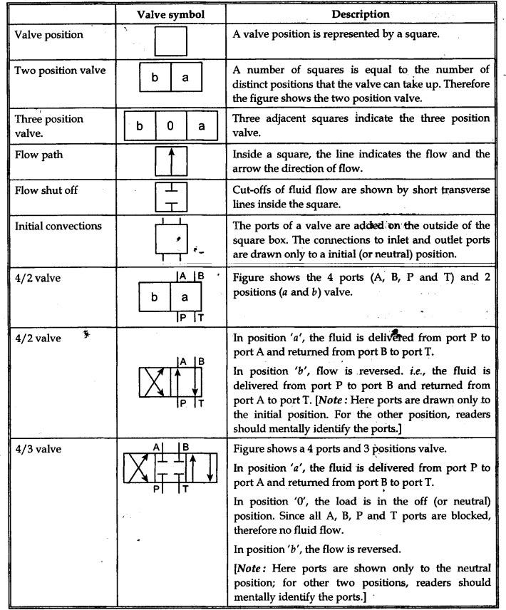
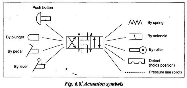
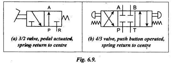
POSITION VALVES • The function of the position valve is to control the introduction of fluid to the lines of the system. When the valve is operated, the liquid lines within it are shifted. • The position valves are usually described by the following relation : (Number of ports/Number of positions) valve. For example, a 4/2 valve has 4 ports and 2 positions. • The ports of a directional control valve are designated by letters, as listed in Table 6.1. Table 6.1. Ports' designations • A direct control valve has two or three working positions generally. They are : 1. Normal or zero position or neutral position. 2. Working positions (such as retract and extend positions). • It is necessary to differentiate between neutral and operating positions. In directional control valves with spring return, the neutral position is defined as the position to which the valve returns after the actuating force has been withdrawn. • In all fluid control systems, the valve positions can be represented by letters a, b, c, and so on, with '0' being used for central neutral position. • The starting (or initial) position is the position taken up by the valve (due to spring in case of spring actuated directional control valve) after installation. The valve attains the working positions when actuated. 3. Valve Symbols For representing valves in circuit diagrams, symbols are used. Generally a valve is represented by a square for each of its switching positions. Two positions are represented by two adjacent squares. It should be noted that symbols show only the functional aspect of the valve and not its principle of design or constructional details. The basic valve symbols and their description are presented in Table 6.2. Table 6.2. Basic valve symbols and their description Note: The above valve symbols are to be used in hydraulic circuits. The corresponding symbols having unfilled arrow heads can be used in pneumatic circuits. 4. Valve Actuation Symbols To obtain complete valve symbols, valve actuations* symbols must be combined with the above basic valve symbols. Fig.6.8 shows symbols for the various ways in which the valves can be actuated. 5. Complete Graphic Valve Symbols Fig.6.9 illustrates how these various symbols can be combined to describe a complete valve operation. Fig.6.9(a) represents a pedal actuated, spring return 3/2 valve. Fig.6.9(b) represents push-button operated, spring return, 4/3 valve. 6. Valve Actuation • In order to respond to the system requirements, we must provide a means of actuation to the hydraulic control valves. • For example, to move the spool in a position valve, to change the setting of a pressure control valve, or to adjust flow-control valves, we need some form of actuation. • Actuation is a method of moving valve element from one position to another. • Types of actuation methods : The four actuation methods normally used are : 1. Manual actuation, 2. Mechanical actuation, 3. Electrical actuation, and 4. Fluid actuation. 1. Manual Actuation • Manual actuation requires action by an operator who must make a control judgement based upon some system requirement. • Manual actuators include levers, push buttons, and pedals. • Manual actuation is commonly used when system requirement is not critical. • It is widely used in machine tools and mobile equipment. 2. Mechanical Actuation • Mechanical actuators include springs, plungers, rollers, cams, and mechanical linkages. • The springs and plungers are most commonly used to provide force for a variety of valve operations. 3. Electrical Actuation • Electrical actuators are nothing but solenoid actuators. • A solenoid is a electromagnetic coil. When it is energized, it creates a magnetic force that pulls the armature. The armature is connected to the spool of the valve and the valve is actuated. • Most applications use 115 V, 60 cps solenoids. Also they are available in a wide range of AC or DC voltages. DC solenoids are quiet in operation, whereas AC solenoids may hum or chatter. • The solenoids are energized by signals from pressure switches, limit switches, or timers which usually operate through power or signal relays to accommodate the current required to actuate the solenoid. • Solenoid actuation provides flexibility in hydraulic system design. System commands can be obtained from signals in any port of the circuit. 4. Pilot Fluid Actuation • Oil or air can be used to provide fluid power for the actuation of valves. • Air can be used to activate single-stage valves, or pilot valves on multistage units. • The advantage of pilot-fluid actuation is the long life of fluid components compared to that of electrical components. • The graphic symbols for various actuation devices are shown already in Fig.6.8. 7. Classification of Position Valves Position valves are classified in terms of the number of fluid ports and the number of valve positions, as (i) Two way, two position valves (2/2 valves). (ii) Three way, two position valves (3/2 valves). (iii) Four way, two position valves (4/2 valves), (iv) Four way, three position valves (4/3 valves), and so on.1. Introduction
2. Valve Position
Hydraulics and Pneumatics: Unit II: Hydraulic Actuators and Control Components : Tag: : Introduction, Valve Position - position valves
Related Topics
Related Subjects

Hydraulics and Pneumatics
ME3492 4th semester Mechanical Dept | 2021 Regulation | 4th Semester Mechanical Dept 2021 Regulation