Hydraulics and Pneumatics: Unit I: Fluid Power Priniciples and Hydraulic Pumps
Pneumatic Power System (layout of a pneumatic system)
Arrangement, Working, Positions of Valve, Advantages, Disadvantages
We know that the pneumatic system uses mostly the compressed air as its fluid medium. Also, pneumatic system is always an open loop system.
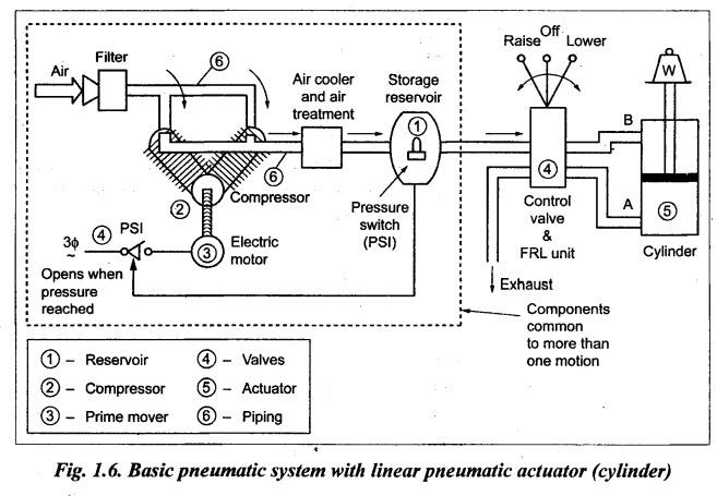
PNEUMATIC POWER SYSTEM (LAYOUT OF A PNEUMATIC SYSTEM) We know that the pneumatic system uses mostly the compressed air as its fluid medium. Also, pneumatic system is always an open loop system. The general arrangement of a basic pneumatic system is shown in Fig.1.6. Like hydraulic system, the pneumatic system also have similar six basic components (Fig.1.6). The basic components and their functions are presented in Table 1.9. Table 1.9. Basic components of a pneumatic system 1. Reservoir (or air tank): An air tank is provided to store the compressed air required for the operations. 2. Compressor: A compressor is used to compress the incoming atmosphere air so as to increase the pressure of the air. 3. Prime mover: A prime mover, usually an electric motor, is used to drive the compressor. 4. Valves: Valves are fitted in the system to control air direction, pressure, and flow rate. 5. Actuator: An actuator is provided to convert the air energy into mechanical force or torque to do useful work. 6. Fluid-transfer piping: Piping is provided to carry the compressed air from one place to another. These pneumatic components are studied in detail in subsequent chapters; compressors are discussed in Chapter 11; pneumatic valves and actuators in Chapter 12; and so on. The total pneumatic system for the task of lifting a weight (W) by a distance (D) is shown in Fig.1.6. The parts enclosed in the dotted-lined box are common to an area of the plant, which may have many linear and rotary actuators. In this case, we use only one linear hydraulic actuator. Air is drawn from the atmosphere through the air filter and raised to the required pressure by an air compressor. Air contains significant amount of water vapour and also the air temperature is raised considerably by the compressor. So the air must be cooled before using it in the system, which results in condensation. The compressed air is stored in the reservoir, which has a water outlet at the bottom of the reservoir and a pressure switch (PSI) to control the pressure of the compressed air (by controlling the motor). Pressure switch stops the motor when the required pressure is attained and starts the motor when the pressure falls down the mark. The outlet of the reservoir is connected to a component called F.R.L. (Filter - Regulator - Lubricator) unit, which does the following activities : (i) Filters the tiny foreign particles from the compressed air. (ii) Regulates the pressure just before entering the system. (iii) Lubricates the compressed air for the pneumatic cylinders. The cylinder movement is controlled by the pneumatic valve. One side of the pneumatic valve is connected to the compressed air line and silencers for the exhaust air and the other side of the valve is connected to port A and port B of the cylinder. Raise: To lift the weight, the compressed air line is connected to port A and the port B is connected to the exhaust air line (silencer B), by moving the valve position to ‘raise'. Lower: To bring down the weight, the compressed air line is connected to port B and the port A is connected to exhaust air line (silencer A), by moving the valve position to 'lower'. Off: The weight can be stopped at a particular position (height) by moving the valve position to 'off'. This disconnects the port A and port B from the pressurized line and the retrieval line, which locks the air in the cylinder. Note 1. Few other key points to be noted in the above pneumatic system are: • One cannot stop the pneumatic cylinder precisely in between the top end position and bottom end position. Most of the industrial applications does not try to stop a pneumatic cylinder in between the ends. • Operating pressure in pneumatic systems are generally much lower than those in hydraulic systems. Therefore pneumatic systems require larger actuators than hydraulic systems for the same load. 2. It should be noted that the pneumatic system is an open loop system. That is, the compressed air after being used in driving the actuator is exhausted back into the atmosphere. On the other hand, the hydraulic system is always a closed loop system. That is, the used hydraulic oil is drained back to the reservoir and is repeatedly reused again and again. Table 1.10 presents the specific advantages of using pneumatic power systems. Table 1.10. Advantages of pneumatic power systems (over hydraulic systems) 1. Since the density of gas (air) is much lower than liquid (oil), the compressed gas (air) can be easily transported/accelerated. 2. Simple construction of pneumatic elements and easier handling. 3. High degree of controllability (of pressure, speed and force of pneumatic medium (air)). 4. Since the viscosity of gas (air) is much lesser than liquid (oil), this results in lesser frictional pressure and power losses. 5. Since pneumatic systems use air, they are cheaper than hydraulic and other systems. 6. The pneumatic systems do not present a fire hazard because of fire-proof characteristics of the medium. 7. Weight of the pneumatic systems are lesser when compared to hydraulic systems. 8. Pneumatic systems have better operational advantages than that of hydraulic systems. 9. Unlike in hydraulic systems, the leakage of pneumatic medium in the pneumatic systems will not affect the operation of the system seriously. Because the pneumatic systems receive the compressed air continuously. Table 1.11 presents some of the major disadvantages of pneumatic systems. Table 1.11. Drawbacks of pneumatic power systems 1. Due to a high fluid (air) compressibility, it is impossible to obtain a precise control of actuator velocities in pneumatic systems. 2. Since pneumatic. pressures are quite low due to the compressor design, the pneumatic systems are suitable only for low load and low power applications. 3. The power-to-size ratio of pneumatic components is small. Note It may be noted that pneumatic power systems should not be considered as competitor for the hydraulic power systems, and vice-versa. Since they are so dissimilar in their characteristics, therefore there are not much problems of selection between them. Usually hydraulic and pneumatic equipment do not compete for the same application. It is also found that a combined circuit (in which oil is used in one part and air in another on the same machine or process) is more efficient than any individual system.1. Arrangement
2. Basic Components of a Pneumatic System
3. Working
4. Positions of Valve
5. Advantages of Pneumatic Power Systems
6. Disadvantages of Pneumatic Power Systems
Hydraulics and Pneumatics: Unit I: Fluid Power Priniciples and Hydraulic Pumps : Tag: : Arrangement, Working, Positions of Valve, Advantages, Disadvantages - Pneumatic Power System (layout of a pneumatic system)
Related Topics
Related Subjects

Hydraulics and Pneumatics
ME3492 4th semester Mechanical Dept | 2021 Regulation | 4th Semester Mechanical Dept 2021 Regulation