Hydraulics and Pneumatics: Unit IV: Pneumatic and Electro Pneumatic Systems
pneumatic cylinder sequencing circuits
Pneumatic and Electro Pneumatic Systems - Hydraulics and Pneumatics
The circuit illustrating fluidic sequencing control of two pneumatic cylinder will be presented in Section 15.6.2.
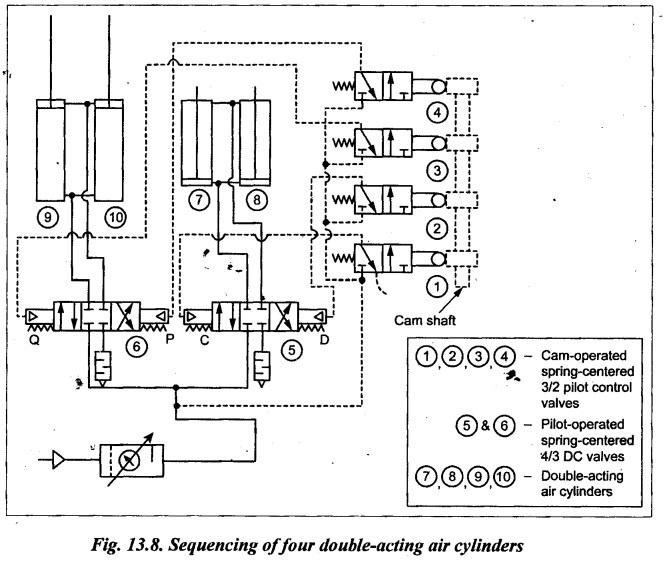
PNEUMATIC CYLINDER SEQUENCING CIRCUITS The circuit illustrating fluidic sequencing control of two pneumatic cylinder will be presented in Section 15.6.2. For more details on this sequencing circuit, refer Chapter 15, Section 15.6.2. 1. Circuit Fig.13.8 illustrates a circuit that provides sequencing control of four double-acting pneumatic cylinders. This circuit uses four cam-operated 3/2 pilot control valves, two pilot- operated 4/3 DC valves, and four double-acting air cylinders. These valves are spring- centered so that when rollers ride off the cams, the valves return to neutral position with all ports closed. 2. Operation First operator engages camshaft drive. As camshaft rotates, cams (1) and (4) depress rollers on 3/2 pilot control valves (1) and (4). From pilot valve (1), air is directed to chamber C of 4/3 DC valve (5). This pilot pressure shifts the position of the 4/3 DC valve (5) to its left mode. When the 4/3 DC valve (5) is shifted to its left envelope flow path configuration, the compressed air flows into blind ends of cylinders (7) and (8), and hence both cylinders (7) and (8) extend. At the same time, air flows through 3/2 pilot control valve (4) to pilot chamber P of 4/3 DC valve (6). This pilot pressure shifts the position of the 4/3 DC valve (6) to its right mode. When the 4/3 DC valve (6) is shifted to its right mode, the air is directed to rod ends of cylinders (9) and (10), and hence both cylinders (9) and (10) retract. As the camshaft rotates 180° angle, cams (1) and (4) release the rollers on 3/2 pilot control valves (1) and (4). Now cams (2) and (3) contact and depress rollers on 3/2 pilot control valves (2) and (3). From pilot valve (2), air is directed to chamber D of 4/3 DC valve (5).* This pilot pressure shifts the position of the 4/3 DC valve (5) to its right mode. When the 4/3 DC valve (5) is shifted to its right mode, the compressed air flows into rod ends of cylinders (7) and (8), and hence both cylinders (7) and (8) retract. At the same time air flows through 3/2 pilot control valve (3) to pilot chamber Q of 4/3 DC valve (6). This pilot pressure shifts the position of the 4/3 DC valve (6) to its left mode. When the 4/3 DC valve (6) is shifted to its left mode, the air is directed to blind ends of cylinders (9) and (10), and hence both cylinders (9) and (10) extends. The cylinder will continue to cycle until the operator disengages the camshaft drive.1. Sequencing Control of Two Air Cylinders
2. Sequencing of Four Double-Acting Air Cylinders
Hydraulics and Pneumatics: Unit IV: Pneumatic and Electro Pneumatic Systems : Tag: : Pneumatic and Electro Pneumatic Systems - Hydraulics and Pneumatics - pneumatic cylinder sequencing circuits
Related Topics
Related Subjects

Hydraulics and Pneumatics
ME3492 4th semester Mechanical Dept | 2021 Regulation | 4th Semester Mechanical Dept 2021 Regulation