Hydraulics and Pneumatics: Unit IV: Pneumatic and Electro Pneumatic Systems
pneumatic circuits
Pneumatic and Electro Pneumatic Systems - Hydraulics and Pneumatics
A pneumatic circuit may be defined as the graphic representation of the pneumatic components in a pneumatically operated machine.
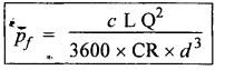
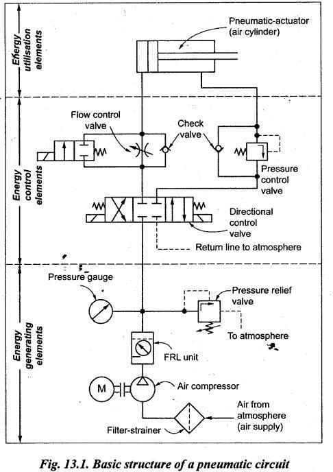
PNEUMATIC CIRCUITS. • A pneumatic circuit may be defined as the graphic representation of the pneumatic components in a pneumatically operated machine. • Pneumatic circuit diagrams can be drawn in similar fashion to the hydraulic circuit diagrams. • Pneumatic circuits are usually used to: (i) control the entry and exit of compressed air in the cylinders; (ii) use one valve to control another valve; and (iii) control actuators or any other pneumatic devices. Though both hydraulic and pneumatic circuits are quiet similar, the two important differences are given below : 1. Unlike in hydraulic systems, pneumatic systems directly exhaust the used air from the air cylinder to the atmosphere. Therefore the return lines are not required in pneumatic circuits. This is depicted by a short dashed line leading from the exhaust port of each valve. • Since fluid power circuits are developed with the use of components' graphic symbols, therefore the readers should be familiar and thorough with the fluid power symbols before they study fluid power circuits. •• The readers may be reminded that the design of hydraulic circuits have been presented in Chapter 8. It is always better to compare and contrast hydraulic circuits with pneumatic circuits to better appreciate the design. construction and features of those circuits. 2. Since most pneumatic circuits use a centralized compressor as their source of energy, generally no input device (such as a pump in a hydraulic circuit) is shown in these circuits. Also the input, to the circuit can be located at some convenient manifold, which leads directly into the FRL (Filter-Regulator-Lubricator) unit. The four important factors should be considered while designing a pneumatic circuit are: 1. Safety of operation, 2. Performance of desired function, 3. Efficiency of operation, and 4. Cost. • Like in hydraulic circuits, there are energy losses due to friction in the pneumatic circuits as well. The energy loss in pneumatics is in the form pressure loss. • Harris formula: The pressure loss of air in a pipeline can be determined using the Harris formula: where Pf = Pressure loss in psi, c = Experimentally determined coefficient, L = Length of pipe in ft, Q = Flow rate in scfm, d = Inside diameter of pipe in inches. • A pneumatic circuit is the symbolic representation of arrangements and connections of various elements of a pneumatic system. • Fig.13.1 illustrates a typical basic structure of a pneumatic circuit. • As could be seen from Fig.13.1, any pneumatic circuit consists of the following main three groups of components: (i) Energy generating elements: These elements include the compressor, filter- strainer, compressor actuating motor, FRL unit, pressure gauges, temperature switches, etc. (ii) Energy control elements: These elements include pressure control valves, flow control valves and direction control valves, check valves, etc. (iii) Energy utilization elements (or actuators): These elements convert the hydraulic energy into mechanical energy. These elements include air cylinders (linear actuators) and air motors (rotary actuators). • For better understanding, various pneumatic circuits can be grouped and presented under the following categories. 1. Single-cylinder pneumatic circuits, 2. Multi-cylinder pneumatic circuits (using cascade method), 3. Electro pneumatic circuits (using ladder diagrams)*, and 4. Pneumatic logic circuits (using fluidic logic controls)**. • The various electro-pneumatic circuits using ladder diagrams are presented in Chapter 14. •• The various pneumatic logic circuits using fluidic logic controls are presented in Chapter 15. • In this chapter, the following basic pneumatic circuits are presented: I. Single-Actuator Circuits 1. Control of a single-acting pneumatic cylinder, 2. Control of a double-acting pneumatic cylinder, (a) Direct control of a double-acting pneumatic cylinder, (b) Air pilot control of a double-acting pneumatic cylinder, and (c) Control of a double-acting pneumatic cylinder using shuttle valve, 3. Semi-automatic control of a double-acting pneumatic cylinder, 4. Automatic pneumatic cylinder reciprocating system, 5. Pneumatic cylinder sequencing circuit, 6. Speed control circuits (or throttling circuits), (a) Meter-in speed control of pneumatic cylinder, (b) Meter-out speed control of pneumatic cylinder, and (c) Speed control of double-acting pneumatic cylinder with two flow control valves. 7. Actuation of pneumatic motor, and 8. Time delay circuit. II. Multi-Actuator Circuits Multi-cylinder pneumatic sequencing circuits for various industrial applications using cascade method.1. What is a Pneumatic Circuit ?
2. Pneumatic Circuits Vs Hydraulic Circuits
3. Factors to be considered
4. Air Pressure Losses in Pipelines

5. Basic Structure of a Pneumatic System
6. Pneumatic Circuits
Hydraulics and Pneumatics: Unit IV: Pneumatic and Electro Pneumatic Systems : Tag: : Pneumatic and Electro Pneumatic Systems - Hydraulics and Pneumatics - pneumatic circuits
Related Topics
Related Subjects

Hydraulics and Pneumatics
ME3492 4th semester Mechanical Dept | 2021 Regulation | 4th Semester Mechanical Dept 2021 Regulation