Hydraulics and Pneumatics: Unit IV: Pneumatic and Electro Pneumatic Systems
plc ladder programs for logic functions
Pneumatic and Electro Pneumatic Systems - Hydraulics and Pneumatics
The logic functions (such as AND, OR, NOR, etc.) can be obtained by combinations of switches (such as limit switches, solenoid coils, etc.).
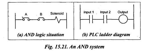
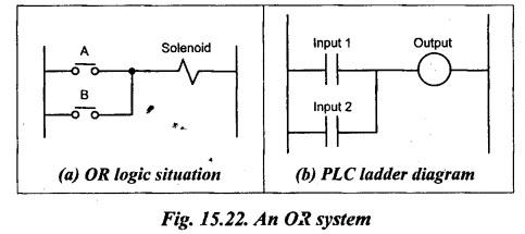
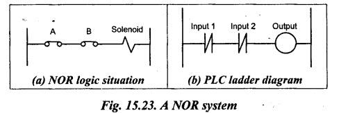
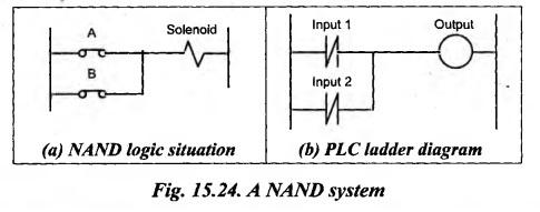
PLC LADDER PROGRAMS FOR LOGIC FUNCTIONS The logic functions (such as AND, OR, NOR, etc.) can be obtained by combinations of switches (such as limit switches, solenoid coils, etc.). The following sections show how we can write PLC ladder programs for such combinations. Fig.15.21(a) shows a situation where a coil is not energized unless two, normally open, switches are both closed. Switch A and switch B have both to be closed, which thus gives an AND logic situation. Fig.15.21(b) shows the PLC ladder diagram for the AND logic function shown in Fig.15.21(a). In Fig.15.21(b), the ladder diagram starts with ||, labelled Input 1, to represent switch A and in series with it ||, labelled Input 2, to represent switch B. The line then terminates with O to represent the output. Fig.15.22(a) shows a situation where a coil is not energized until either, normally open, switch A or B is closed. This situation is an OR logic gate. Fig.15.22(6) shows the PLC ladder diagram for the OR logic gate shown in Fig.15.22(a). In Fig.15.22(b), the ladder diagram starts with | |, labelled Input 1, to represent A and in parallel with it | |, labelled Input 2, to represent switch B. The line then terminates with O to represent the output. Fig.15.23(a) shows a NOR logic gate situation. Fig.15.23(b) shows the PLC ladder program for the NOR gate shown in Fig.15.23(a). Since there has to be an output when neither A nor B have an input and when there is an input to A or B the output stops, the ladder program shows Input 1 in parallel with Input 2, with both being represented by normally closed contacts. Fig.15.24(a) shows a NAND logic gate situation. Fig.15.24(b) shows the PLC ladder program for the NAND gate shown in Fig.15.24(a). There is no output when both A and B have an input. Thus for the ladder program line to obtain we require no inputs to Input 1 and to Input 2.1. AND Logic Function
2. OR Logic Function
3. NOR Logic Function
4. NAND Logic Function
Hydraulics and Pneumatics: Unit IV: Pneumatic and Electro Pneumatic Systems : Tag: : Pneumatic and Electro Pneumatic Systems - Hydraulics and Pneumatics - plc ladder programs for logic functions
Related Topics
Related Subjects

Hydraulics and Pneumatics
ME3492 4th semester Mechanical Dept | 2021 Regulation | 4th Semester Mechanical Dept 2021 Regulation