Hydraulics and Pneumatics: Unit IV: Pneumatic and Electro Pneumatic Systems
plc control of a hydraulic cylinder
Pneumatic and Electro Pneumatic Systems - Hydraulics and Pneumatics
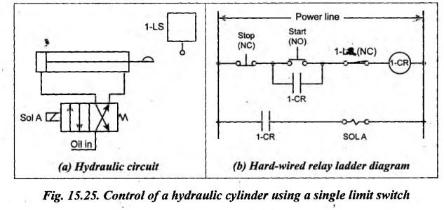
Consider a system, shown in Fig.15.25, which is used to control a double-acting hydraulic cylinder using a single limit switch.
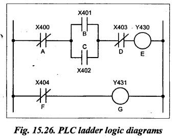
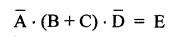
PLC CONTROL OF A HYDRAULIC CYLINDER Consider a system, shown in Fig.15.25, which is used to control a double-acting hydraulic cylinder using a single limit switch. Fig.15.25(b) shows the hard-wired relay ladder diagram for system shown in Fig.15.25(a). Fig.15.26 shows a PLC ladder logic diagram for the equivalent hard-wired relay ladder diagram shown in Fig.15.25(b). It may be noted that the layout of both diagrams are similar. The two rungs of the relay ladder diagram are converted to two rungs of the PLC ladder logic diagram. Since the input modules act like relays, the relay contacts are substituted for original switch contacts (with the prefix X followed by a number) and output modules are substituted by relay coils (with the prefix Y followed by a number). We know that the PLC performs operations based on logic functions. Each rung of a ladder diagram be represented by a Boolean equation. For this purpose, the capital letters A, B, C, etc. are used to represent each electrical component in the Fig.15.36. Now the Boolean equations can be written for each rung as follows: Top Rung: This equation can be read as: NOT A AND (B OR C) AND NOT D EQUALS E. We know that OFF state can be represented by 0 and ON state by 1. This equation means that E is energized when A is NOT actuated AND B OR C is actuated AND D is NOT actuated. Bottom rung: F = G This means that G is energized when F is actuated.1. Circuit and Relay Ladder Diagram
2. PLC Ladder Logic Diagram
3. Boolean Equations
Hydraulics and Pneumatics: Unit IV: Pneumatic and Electro Pneumatic Systems : Tag: : Pneumatic and Electro Pneumatic Systems - Hydraulics and Pneumatics - plc control of a hydraulic cylinder
Related Topics
Related Subjects

Hydraulics and Pneumatics
ME3492 4th semester Mechanical Dept | 2021 Regulation | 4th Semester Mechanical Dept 2021 Regulation