Manufacturing Technology: Unit III: Reciprocating Machine Tools
planing machines
Reciprocating Machine Tools - Manufacturing Technology
In planer, the workpiece mounted on the table reciprocates but the tool is stationary.
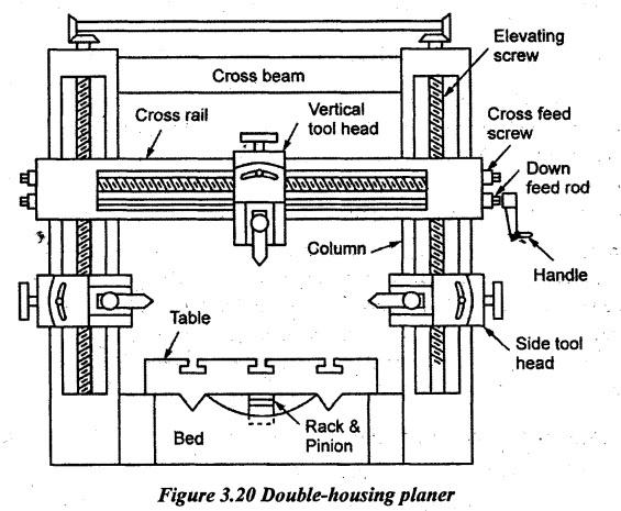
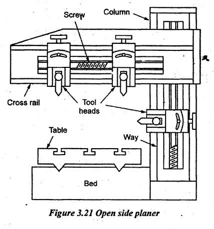
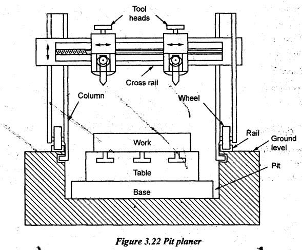
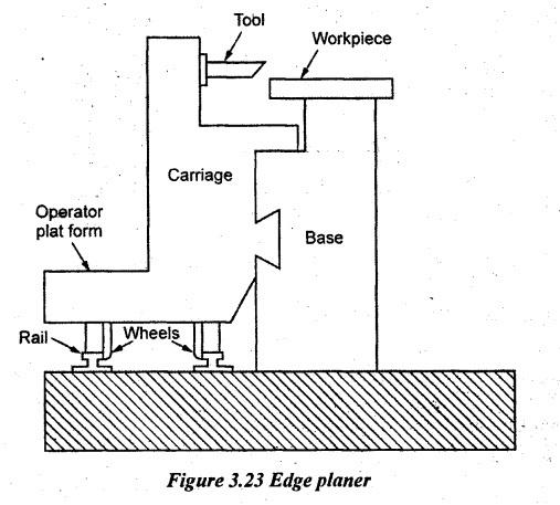
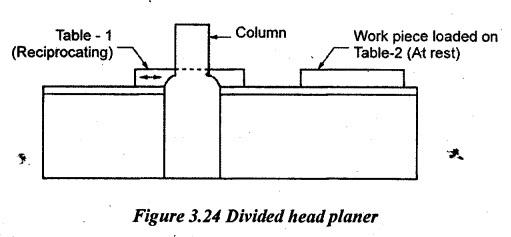
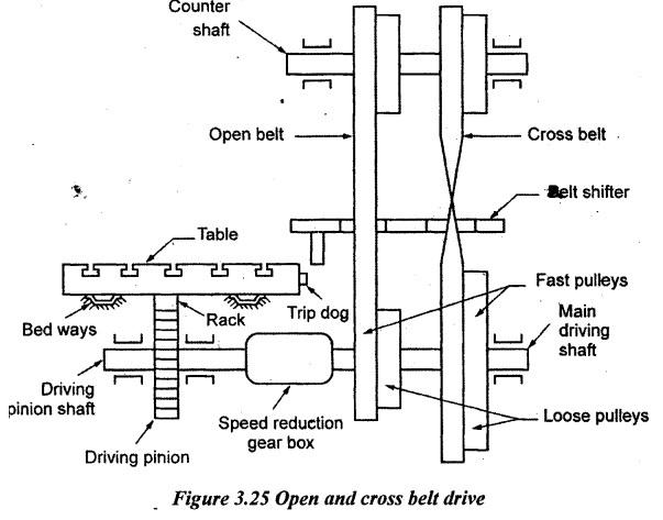
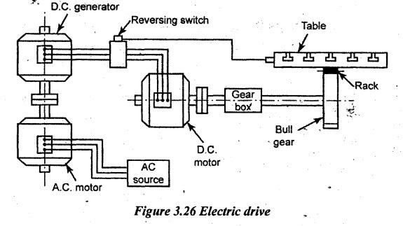
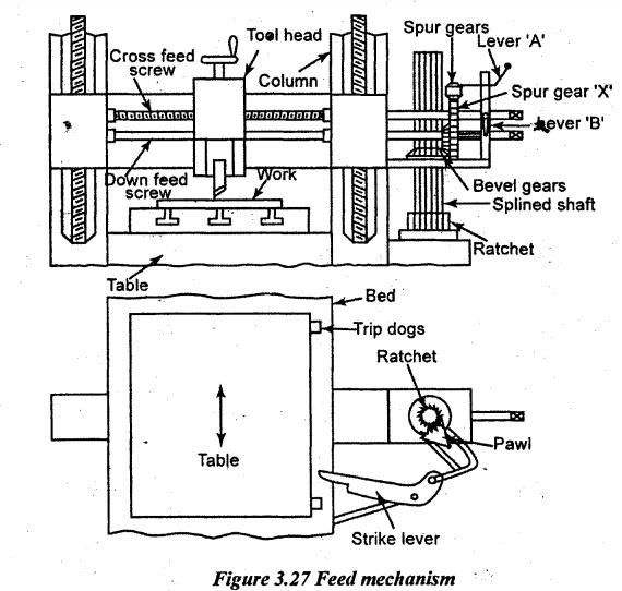
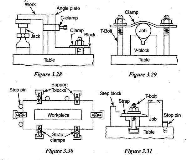
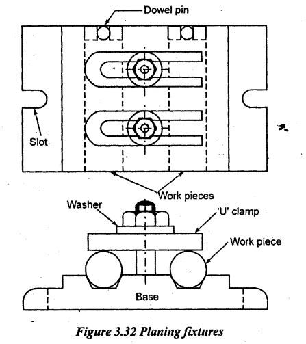
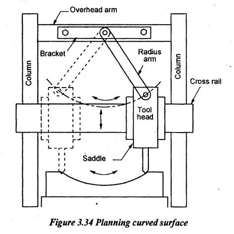
PLANING MACHINES In planer, the workpiece mounted on the table reciprocates but the tool is stationary. A single point cutting tool is used for machining the work surface. This tool is always fitted vertically the tool holder which moves on a cross-rail while feeding. Planer is mainly used for machining large and heavy workpieces. The machined surface may be horizontal, vertical or inclined surface. Planer is a very large reciprocating machine tool. The work is mounted on the table by any one of the work holding devices. Two vertical columns with vertical guide ways are provided on both sides of the bed and connected by a cross-rail to mount the tool heads and also connected by a cross beam at the top. These tool heads are used to hold the tools. The tool cuts the workpiece when the table reciprocates. The cross feed is given by moving the tool head along the cross rail and the vertical feed is given by moving down the tool. The tool slide can be tilted or swiveled at any required angle using a swivel head for machining inclined surfaces. The feed can be given by both manually and automatically. The horizontal movement of the cross rail can be done on the guide ways vertically and vertical movement by elevating screw. In planer also, the metal is removed during the cutting stroke called forward stroke and no metal is removed during the return stroke called idle stroke. Hence, cutting stroke takes place at a slower speed and return stroke with faster speed. Feeding is given at the each end of the cutting stroke. To obtain the quick return of the table, the planer is also driven by a quick return mechanism to reduce the time of return stroke. So, the planer is used for machining heavy and large casting. Example: Lathe bed guide ways, machine guide ways etc. The various types of planer are as follows: 1. Double hosing planer 2. Open side planer 3. Pit planer 4. Edge planer 5. Divided table planer. 1. Double-Housing Planing Machine The double-housing planer has the following parts: 1. Bed 2. Table 3. Columns 4. Cross rail 5. Tool head. 1. Bed: The bed is a very strong and rigid of box type which is made by casting process. The bed length is made twice the length of table with 'V' guide ways. The table is mounted over the bed which houses various mechanisms. Cross ribs are used to increase the strength of the bed. 2. Table: It is also a box type structure which reciprocates on the bed guide ways. It is also having 'T" slots [reamed holes at regular intervals, stop pins and troughs] as that of shaper for clamping the workpiece. 3. Columns: The two long structural member along with guide ways provided on both sides of the member. The two long columns connected by a cross rail and cross beam. The cross rail slides on these guide ways. It carries feed mechanism and power transmission links. 4. Cross rail: It is a rigid structural member mounted between two columns and slides on the guide ways already provided on the columns. The cross-rail can be set or clamped at any height. It carries tool heads. 5. Tool heads: Maximum four tool heads can be mounted on the planer. Two are on the cross rail and another two are on the guide ways of both the columns. It may tilt to any required angle. 2. Open Side Planing Machine The only difference in this type is that only one vertical column is provided on one side of the bed and other side is left free. So, large and heavier jobs can be mounted on the table. The construction and working principle are same as that of a double housing planer. 3. Pit Planing Machine The working principle of this planer is similar to other types of planer. But the table of the planer is kept in a pit as the floor coincides with the top surface of the table. So, heavy and large work can be held and machined easily. 4. Edge Planing Machine In this type of edge planer, the bed and table are stationary and the tool head is mounted on a carriage. The carriage can be moved longitudinally on guide ways. A platform is provided to stand and travel along with it while machining. It is mainly used for machining the edges of steel plates. 5. Divided Table Planing Machine The working principle is similar to a standard planer. But it has two reciprocating tables. Generally, the time required to set the work on the planer is more. To reduce the setting time of work, the two same machining are combined by using two tables. When the first job is machining, that first table will be only reciprocated and the second table is stationary. On that time, the setting of work can be carried out. After machining the first workpiece, the table is brought to rest and next one work is set on it. On that time, the second table is in machining operation. Generally, the planers are specified by the following parameters as below. 1. The distance between two columns. 2. Stroke length of the planer. 3. Radial distance between the top of the table and the bottom most position of the cross rail. 4. Maximum length of the table. 5. Power of the motor. 6. Range of speeds and feed available. 7. Type of drives required. The following various types of quick return mechanism are used in planer as described below: 1. Open and Cross Belt Drive A counter shaft is driven by electric motor. This shaft carries two wide faced pulleys of equal diameter. One pulley drives the open belt. Another pulley drives the cross belt. The main driving shaft is placed below the bed. One end of the shaft carries a set of two large pulleys and two small pulleys. One of the larger pulley and one of the smaller pulleys are keyed to the shaft. They are called fast pulleys. The other two pulleys rotate freely on the shaft. They are called loose pulleys. The large pulleys are connected to the counter shaft pulleys by cross belt. The small pulleys are connected to the counter shaft pulleys by open belt. The speed of the main driving shaft is reduced through a speed reduction gearbox. From this gearbox, the drive is transmitted to the driving pinion. This pinion meshes with the rack at the bottom of the table. Referring to the Figure 3.25, the cross belt connects the larger loose pulley. No drive is transmitted by it to be main shaft. But the open belt connects the smaller fast pulley. So, the drive is transmitted to the main shaft through the open belt. The return stroke of the table takes place. At the end of the return stroke, the trip dog pushes the belt shifter. The belt shifter shifts both the belts to the right. The cross belt is shifted to the larger fast pulley. The open belt is shifted to the smaller loose pulley. So, the drive is transmitted to the main shaft through the belt on the larger fast pulley. The direction of rotation of the main shaft is reversed. Because of the larger diameter of the pulley, the main shaft rotates at a slow speed. So, the cutting stroke takes place at slow speed. No drive takes place through the open belt. The quick return motion is obtained. At the end of the cutting stroke, the belts will be shifted to the left by another trip dog. The length and position of the stroke may be adjusted by adjusting the position of trip dogs. 2. Electric Drive or Ward-Leonard drive In this drive, four electrical machines are used in which one is D.C. motor with variable speed reversible motor. The D.C. motor shaft is connected to the table through gears rack and pinion. This D.C. motor receives power from a D.C. generator. This D.C. generator is again coupled with one more A.C. motor. Working principle When the A.C. motor runs, the D.C. motor will receive power from the D.C. generator. At that time, the table moves in forward direction. At the end of this stroke, a trip dog actuates an electrical reversing switch. Due to this action, it reverses the direction of current in D.C. generator with increased current strength. Now, the motor rotates in reverse direction with higher speed. So, the table moves in reverse direction to obtain quick return motion. Advantages: 1. Operation is smooth. 2. More number of cutting speeds and returns speeds can be obtained. 3. Quick and accurate controls are possible. 4. Cutting speed, stroke length and stroke position can be adjusted without stopping the machine. 1. Hand Feed The cross feed screw passes through a nut in the tool head. When this cross feed screw rotates, the tool will move in horizontal direction to obtain cross feed. 2. Automatic Feed A trip dog fitted on the planer table continuously actuates a lever to give continuous forward and return stroke. During actuation, the lever moves and rotates a pawl. On that time, the vertical splined shaft attached with the ratchet will also be rotated. The bevel gear engaged with this splined shaft will slide up and down. This bevel gear is cast integral with a spur gear. It is for rotating the down feed rod freely by moving the lever 'B'. The spur gear is engaged with another spur gear fitted with cross feed screw. It transmits power to the tool head. It is known as cross feed. At the end of the forward stroke, the lever strikes by the trip dog to bring the lever to its original position. On that time, the pawl slips over the ratchet. But it will not rotate. To obtain automatic down feed, the spur gear fitted to the cross feed screw is disengaged by moving the lever. Now, the tool head moves in downward direction. Mostly, works are clamped directly on the table by using 'T' bolts and clamps. These ‘T” - bolts and clamps are fixed on the table having holes on regular intervals. The following clamping devices are listed below: 1. Angle plate 2. Planer jacks 3. Stop block 4. Adjustable screw stop. 1. Angle plate: In this method, 'T" bolts and strap clamps are combinedly used on all sides. 2. Planer jacks: It is used to support a workpiece at one end. The planer jack is nothing but an integral part of jack, C-clamp, angle plates and 'T” bolts. 3. Stop block: Here also, 'T' bolts with step block and stop pin are used to hold the workpieces rigidly. 4. Other work holding devices: 'V’ blocks, 'T’ bolts and clamps are used to clamp cylindrical workpieces. 5. Planing fixtures: For producing larger quantities, planing fixtures are used. It is mainly used for machining flat surface on an axle. It has a steel base with two 'V' grooves which locates the axle in correct position. Studs are mounted in between 'V' grooves. It is used to clamp the workpiece by using 'U' clamps. Generally, the tools used in planer are made heavier and larger in cross section to withstand heavy cut. The tools may be solid, forged or bit type and also it may be of H.S.S. and tungsten carbide. All the tools used in planer are single point cutting tools. To perform horizontal surfaces, right hand or left hand straight tools are used. Rough cutting tools are used to remove more amount of stock and finishing tool is used for finishing. The following operations generally performed in a planer are: 1. Planing horizontal surface 2. Planing of an angle 3. Planing vertical surface 4. Planing curved surface. 1. Planing Horizontal Surface The work is clamped rigidly on the table. Right or left hand tool is used and held on the tool post. Necessary feed and speed required are selected. The depth of cut is given by feeding the down feed screw but the feed is given through rotating cross feed. The setting of tool in the head is same that of shaper. First roughening cuts and then finishing cuts are taken to finish the work completely. Both tool heads are used to larger size workpiece. 2. Planing Vertical Surface Here also, the work is held rigidly on the table. Clamps should not be provided at the side of the work as per the clamping principle. The vertical slide of the tool post is adjusted perpendicular to the planer table. The apron is swiveled to certain angle which prevents the dragging over the tool during return stroke. The speed and feed should be selected properly. By rotating the cross feed screw, the depth of cut is given. Feed is given by rotating the down feed screw. The vertical surface of the workpiece is finished by using bend tool. For this purpose, the slide of the tool head is made perpendicular to the workpiece. Swiveling the apron is not necessary. Feed is given by moving the tool head in the vertical direction. 3. Planing Angular Surface Angular surfaces such as V- grooves, dovetail machining is done in planer in the same manner as that of shaper. The tool is set in the vertical tool head. The vertical slide is set to the required angle. This is for providing necessary relief to the cutting edge of the tool. Feed is given by the down feed screw. The tool moves in angular direction. 4. Planing Curved Surfaces A special attachment is used for machining curved surfaces. Figure 3.34 illustrates this attachment which consists of a radius arm and a bracket. The bracket is fitted to the overhead arm. One end of the radius arm is pivoted to the bracket whereas the other end is connected to the vertical slide of the tool head. At this position, down feed screw of the tool head is disengaged. Now, the tool head moves crosswise and the slide moves up and down by rotating the cross feed screw. As both the movement takes place at a time, the tool moves in a curved path. Thus, it produces curved surface. The calculations of speed, feed, depth of cut and machining time are similar to a shaping machine. The only difference between shaper and planner is tool and workpiece movements.1. PRINCIPLE OF OPERATION
2. TYPES OF PLANING MACHINES
3. SIZE OR SPECIFICATIONS OF A PLANING MACHINE
4. MECHANISM IN PLANING MACHINES
5. FEED MECHANISM
6. WORK HOLDING DEVICES IN PLANING MACHINES
7. TOOLS USED IN PLANING MACHINES

8. OPERATIONS PERFORMED ON PLANING MACHINES
9. CUTTING SPEED, FEED, DEPTH OF CUT AND MACHINING TIME
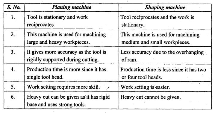
10. DIFFERENCE BETWEEN SHAPING MACHINE AND PLANING MACHINE
Manufacturing Technology: Unit III: Reciprocating Machine Tools : Tag: : Reciprocating Machine Tools - Manufacturing Technology - planing machines
Related Topics
Related Subjects

Manufacturing Technology
ME3493 4th semester Mechanical Dept | 2021 Regulation | 4th Semester Mechanical Dept 2021 Regulation