Hydraulics and Pneumatics: Unit I: Fluid Power Priniciples and Hydraulic Pumps
pascal's law (principle of pressure)
Fluid Power Priniciples and Hydraulic Pumps - Hydraulics and Pneumatics
Pascal's law states that the pressure generated at any point in a confined fluid acts equally in all directions.
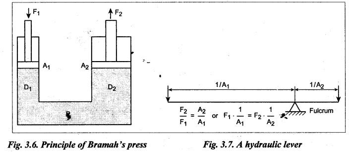
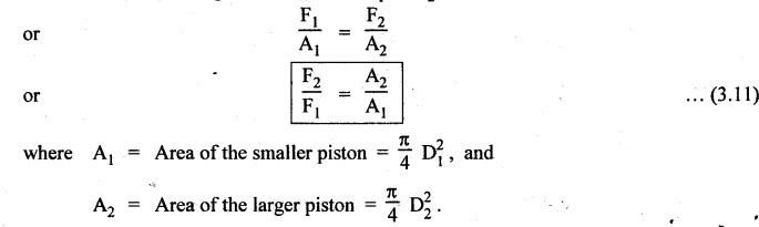
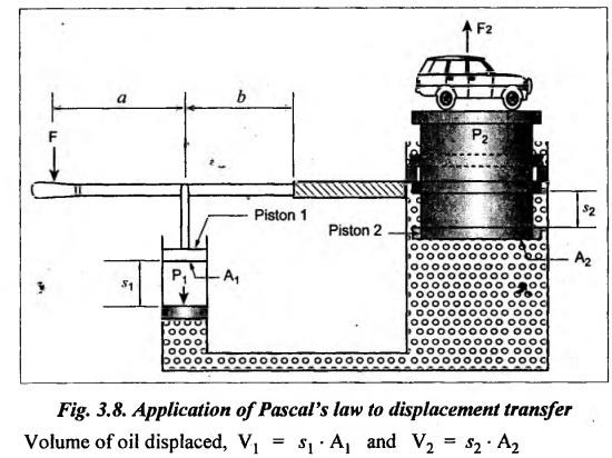
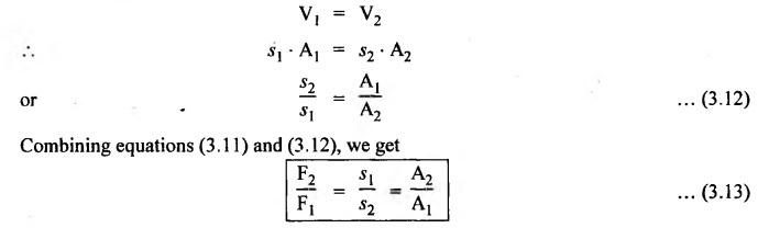
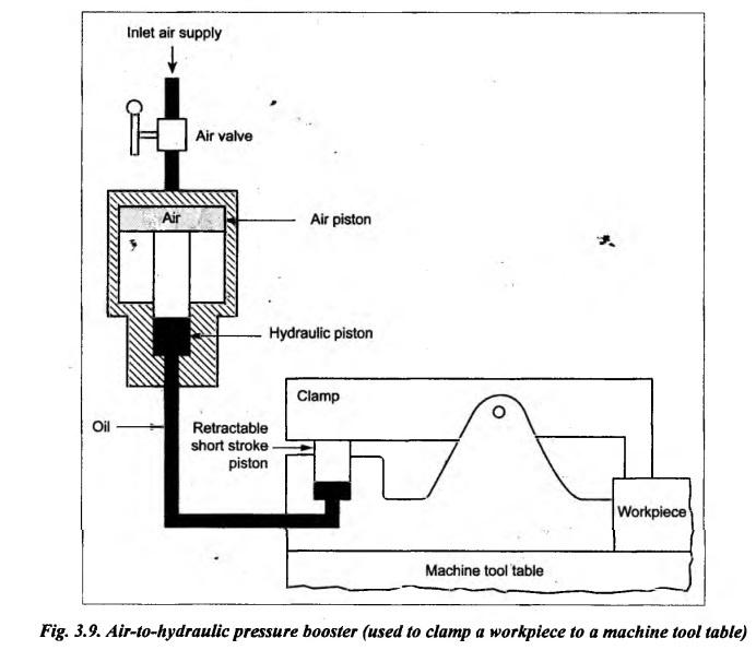
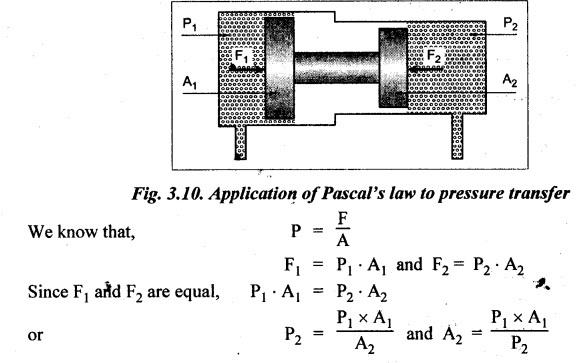
PASCAL'S LAW (PRINCIPLE OF PRESSURE) • Law: Pascal's law states that the pressure generated at any point in a confined fluid acts equally in all directions. • The law can also be stated that pressure applied to a confined fluid is transmitted undiminished in all directions. • The Pascal's law reveals the underlying principle of how fluid power system work. This law applies to a fluid (i.e., both liquid and gas) at rest. • Illustration: The Pascal's law is illustrated in Fig.3.5 where a force F is applied on the confined liquid in the jar. This produces a pressure P at every point within the fluid, which acts with equal pressure on the inside walls of the container. This law is named after the scientist Blaise Pascal who has developed the principle of fluid power in 1648. 1. Bramah's Hydraulic Press (Amplification of Hydraulic Force) The Bramah's hydraulic press was developed by applying the Pascal's law. In a hydraulic press, a small input force is applied to generate a large output force. That is, the hydraulic press amplifies the hydraulic force in the hydraulic systems. Working Consider two oil containers both in cylindrical form and connected together contain some oil, as shown in Fig.3.6. Both the cylinders have a piston having different diameters says D1 and D2 respectively, where D1 is smaller than D2. If a force F1 is applied to the small-diameter piston, then this will produce an oil P1 at the bottom of the piston 1. Now this pressure is transmitted through the oil to the large- diameter piston 2. Because the piston 2 has a larger area (A2), the pressure at the bottom of the piston 2 will be P2. Now this pressure P2 will push up the piston 2 to create an output force F2. We know that according to Pascal's law, P1 = P2 It is named after an English Engineer Joseph Bramah who has developed it in 1795. Since A2 > A1 (i.e., A2/A1 > 1), therefore F2 will be higher than F1. In other words, the hydraulic press amplifies the hydraulic force. It may be noted that the hydraulic press arrangement shown in Fig.3.6 is equivalent to a mechanical lever as shown in Fig.3.7 with the length of the lever arms being inversely proportional to the piston areas. 2. Hydraulic Jack (Transmission of Displacement) To lift the load F2 by a distance s2, the piston P1 must displace specific quantity of liquid by moving by a distance s1, as shown in Fig.3.8. Since the displacement volume is identical, From the equation (3.13), one can conclude that in a hydraulic press, the output force is greater than the input force, but the output movement will be lesser than the input movement. The equation (3.13) can be rewritten as F1 s1 = F2 s2 ...(3.14) We know that energy is the product of force and the distance moved by the force. Thus from equation (3.4), we can state that the energy input to the hydraulic press equal the energy output from the press 3. Air-to-Hydraulic Pressure Booster • Use: The air-to-hydraulic pressure booster is a device used for converting compressed air into the higher hydraulic pressure, which is required for operating hydraulic cylinders. Such device can be found in various applications such as booster-powered riveting pressure, and booster-powered clamps on milling machines. • Construction: Fig.3.9 illustrates an air-to-hydraulic pressure booster arrangement, which is commonly employed to clamp workpiece to a machine tool table. Working: If the air piston (having a area A1) is subjected to air pressure P1, then the air will produce a force F1 on the hydraulic cylinder piston. If the area of the hydraulic piston is A2 (such that A2 << A1), then the hydraulic discharge oil pressure will be P2. Now, as per Pascal's law, this oil pressure P2 will be used for clamping a workpiece to a machine tool table, as shown in Fig.3.9. The pressure ratio of an air-to-hydraulic pressure can be calculated by using the relation : 4. Pressure Transfer Pressure P1 produces force F1 on the area A1, which is transferred through the piston rod to the other end with force F2, acting on area A2, and producing pressure P2. This is illustrated in Fig.3.10.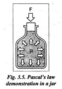
1. Applications of Pascal's Law

Hydraulics and Pneumatics: Unit I: Fluid Power Priniciples and Hydraulic Pumps : Tag: : Fluid Power Priniciples and Hydraulic Pumps - Hydraulics and Pneumatics - pascal's law (principle of pressure)
Related Topics
Related Subjects

Hydraulics and Pneumatics
ME3492 4th semester Mechanical Dept | 2021 Regulation | 4th Semester Mechanical Dept 2021 Regulation