Engineering Graphics: Unit II (b): Projections of Points
Orthographic Projections of a Point
Engineering Graphics (EG)
Consider a point A situated in First Quadrant, x units, in front of VP, y units above HP amd z units in front of PP as shown in Fig. 11.5.
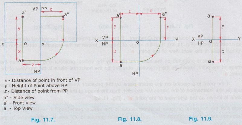
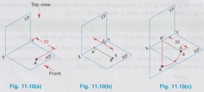
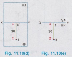
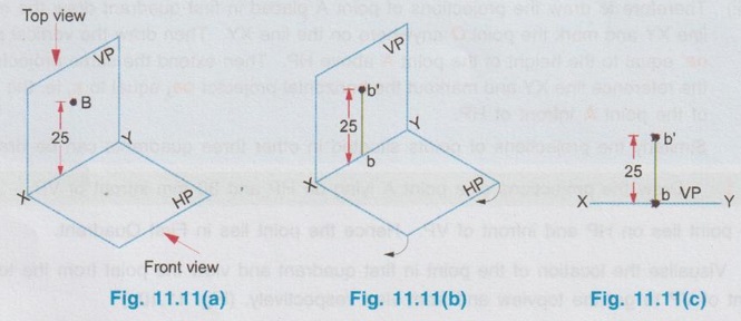
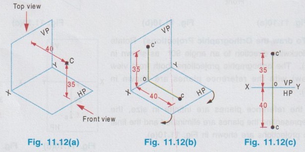
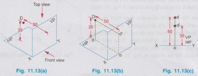
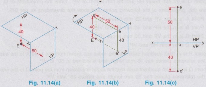
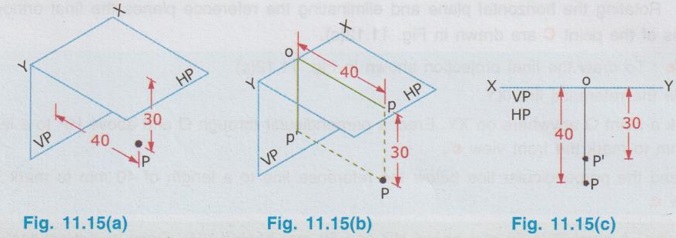
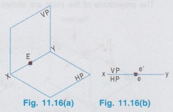
ORTHOGRAPHIC PROJECTIONS OF A POINT Consider a point A situated in First Quadrant, x units, in front of VP, y units above HP amd z units in front of PP as shown in Fig. 11.5. The orthographic projections of this point A is drawn as below: Step 1: Visualise the point A in first quadrant in pictorial view as shown in fig. 11.6 and get the views of the point A as a, a', and a" on HP, VP and PP respectively. Step 2: Visualise the vertical projector oa' (equal to y units) and visualise the horizontal projector oa (equal to x units) and visualise the point of intersection of these projectors with the reference axis at O. Step 3: As we have seen in the previous chapter, imagine that the HP is rotated in clockwise direction and rotate the PP in anticlockwise direction at 90° as shown below in fig. 11.7. Note: (i) 11.5 The planes HP, VP and PP are of infinitive size. Hence the rectangles representing the planes are removed and the projections of the point A is obtained as shown in Fig. 11.8. (ii) In general only front view and top view are drawn for a point. Thus if side view of the point A is eliminated, the final projections of the point A are shown in Fig. 11.9. (iii) Therefore to draw the projections of point A placed in first quadrant draw the reference line XY and mark the point O anywhere on the line XY. Then draw the vertical projector oa' equal to the height of the point A above HP. Then extend the same projector below the reference line XY and markout the horizontal projector oa, equal to x, ie. the distance of the point A infront of HP. Similarly the projections of points situated in other three quadrants can be drawn. Example 1: Draw the projections of a point A lying on HP and 30 mm infront of VP. The point lies on HP and infront of VP. Hence the point lies in First Quadrant. Step 1: Visualise the location of the point in first quadrant and view the point from the top of HP and infront of VP to get the topview and front view respectively. (Fig. 11.10a) Step 2: (To draw the Front View) The Point is projected by the horizontal projector to the vertical plane as shown in Fig. 11.10(b). Front view is a' seen on XY axis. Step 3 (To draw the top view) The point is projected by the vertical projector to the horizontal plane as shown in Fig. 11.10(b). Since the point lies on the HP, the actual point A itself is its top view. Step 4 (To draw the Orthographic Projections) Rotate the HP in clockwise direction to an angle 90° as shown in Fig. 11.10(c). The orthographic projections (both front view and top view) with the reference planes are shown in Fig. 11.10(d). Since the reference planes are infinite in size, the rectangles representing the planes are eliminated and the final orthographic projections are shown in Fig. 11.10(e). Note: Final orthographic projections may be drawn directly as shown in Fig. 11.10(e) using free hand sketch. Example 2: Draw the projections of a point B lying on VP and 25 mm above HP. The point B is above HP and on VP. Hence the point B lies in first quadrant. Step 1: The point B is located as shown in fig. 11.11(a) and observed from the front of VP and top of HP as shown in fig. 11.11(a). Step 2: The projections of the point B are obtained by the projectors as shown in fig. 11.11(b). The point b' (the actual point B itself, since the point lies on VP) is the front view and the point b (lies on reference axis XY) is the top view. Step 3: The HP is rotated to 90° in clockwise direction and the reference planes are removed. The final orthographic projections of the point is shown in fig. 11.11(c). Example 3: Draw the projections of a point C which is 35 mm above HP and 40 mm infront of VP. The point is above HP and infront of VP. Hence the point lies in first quadrant. Step 1: The point is observed as shown in Fig. 11.12(a) to draw the front view and top view. Step 2: The images of the point (ie, front view c' and top view c) and the corresponding projectors are shown on the reference planes as shown in Fig. 11.12(b). Step 3: Rotating the horizontal plane and eliminating the reference planes the final orthographic projections of the point C are drawn in Fig. 11.12(c). Note: To draw the final projection shown in Fig. 11.12(c). Draw the reference line XY. Mark a point O anywhere on XY. Erect a perpendicular through O and above HP to a length of 35mm to mark the front view c'. Extend the perpendicular line below the reference line to a length of 40 mm to mark the top view c. Example 4: A point D is 35 mm above HP and 50 mm behind VP. Draw its projections. The point is above HP and behind VP. Hence the point is in second quadrant. The projections of the point are shown in Fig. 11.13(c). Example 5: A point E is 40 mm below HP and 50 mm behind VP. Draw its projections. The point is below HP and behind VP. Hence the point is in third quadrant. The orthographic projections of the given point are shown in fig. 11.14(c). Example 6: Draw the projections of a point P, which is 30 mm below HP and 40 mm infront of VP. The point is below HP and infront of VP. Hence the point is in fourth quadrant. The final orthographic projections of the point are shown in fig. 11.15(c). Example 7: Draw the projections of a point E, which lies in both HP and VP. The point lies in both HP and VP. ie, the point lies on the reference axis as shown in Fig. 11.16(a). Its orthographic projections are shown in Fig. 11.16(b). When the point is observed from front its front view e' coincides with the actual point. Similarly when the point is observed from top its top view e coincides with the actual point (or) its front view. Thus both front view and top view are the actual point lies on the reference axis XY as shown in Fig. 11.16(b).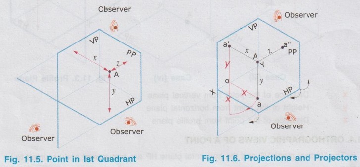
Engineering Graphics: Unit II (b): Projections of Points : Tag: : Engineering Graphics (EG) - Orthographic Projections of a Point
Related Topics
Related Subjects

Engineering Graphics
GE3251 eg 2nd semester | 2021 Regulation | 2nd Semester Common to all Dept 2021 Regulation