Hydraulics and Pneumatics: Unit IV: Pneumatic and Electro Pneumatic Systems
non-return valves
Pneumatic and Electro Pneumatic Systems - Hydraulics and Pneumatics
As the name suggests, non-return valves permit flow of air in only one direction and completely restrict the flow of air in other direction.
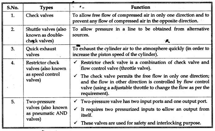
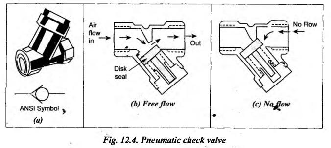
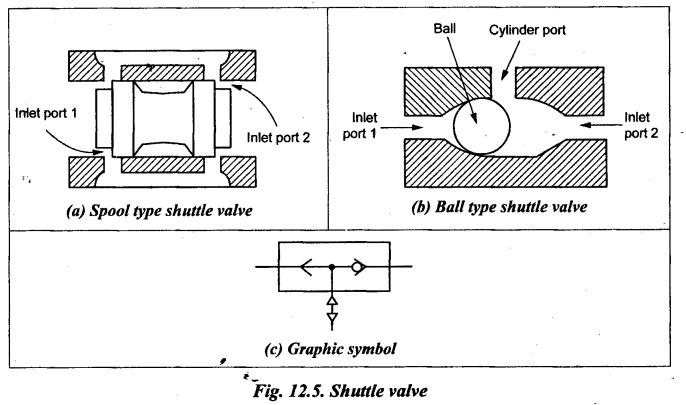
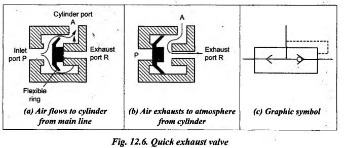
NON-RETURN VALVES • As the name suggests, non-return valves permit flow of air in only one direction and completely restrict the flow of air in other direction. • Types: Important non-return valves and their functions are presented in Table 12.1. Table 12.1. Types of non-return valves and their functions 1. What are Check Valves ? • Check valves are the most commonly used and the simplest type of directional control valves. • Functions: The check valves are used: (i) to allow free flow of compressed air in only one direction, and (ii) to prevent any flow of compressed air in the opposite direction. • Since check valves block the reverse flow of the fluid, they are also known as non- return valves. 2. Construction and Operation The sectional view and ANSI symbol of pneumatic check valve are shown in Fig.12.4(a). The construction and operation of a typical pneumatic check valve is illustrated in Figs. 12.4(b) and (c). As shown in Fig.12.4(b), when flow is in the forward direction, the compressed air pressure pushes the disk seal and thus the valve allows free flow. Instead, if flow is attempted in the opposite direction as shown in Fig.12.4(c), the compressed air pushes the disk seal in the closed position. Hence no flow is permitted in opposite direction. 1. What are Shuttle Valves ? • Shuttle valves, also known as double check valves, are used when control is required from more than one power source. • In other words, shuttle valves are used to select the higher of the two input pressures automatically and connects to output port. This valve is also known as 'OR GATE’. 2. Construction and Operation The construction and operation of a typical three port spool-type shuttle valve is illustrated in Fig.12.5(a). The alternative ball-type shuttle valve for the same purpose is shown in Fig.12.5(b). As shown in Figs.12.5(a) and (b), this valve consists of two inlet ports and one outlet port. As long as pressure in the right inlet port is greater than the left, the spool (or ball) closes the left port. When pressure at the left port becomes greater than at the right, the spool (or ball) moves to the right, closing the right port and opening the left. 3. Graphic Symbol Fig.12.5(c) shows the graphic symbol of a shuttle valve. 1. What is a Quick Exhaust Valve ? • A quick exhaust valve is a typical shuttle valve. The quick (or fast) exhaust valve is used to exhaust the cylinder air to the atmosphere quickly. • It is basically used with spring return single-acting pneumatic cylinders to increase the piston speed of cylinders. • The higher speed of piston in a cylinder is possible by reducing the resistance to flow of the exhausting air during motion of the cylinder. The resistance can be reduced by expelling the exhausting air to the atmosphere quickly by using a special valve. That's why this valve is known as a quick exhaust valve. 2. Construction and Operation The construction and operation of a typical quick exhaust valve is shown in Fig.12.6. It consists of a movable disc and three ports—an inlet port (P), and exhaust port (R), and a cylinder port (A). Its working principle is very much similar to that of a shuttle valve. When the air flowing to the cylinder from the DC valve is applied at port P, then the flexible ring covers the exhaust port R, whereby the compressed air passes from port P to the cylinder through port A (Fig. 12.6(a)). But the return air from the cylinder pushes the flexible ring to cover the inlet port P, whereby the exhaust air immediately expelled to the atmosphere (Fig.12.6(b)). Thus the resistance to piston movement is reduced considerably and the speed of the piston in the cylinder is accelerated proportionately. 3. Graphic Symbol Fig.12.6(c) shows the graphic symbol of a quick exhaust valve.1. What are Non-Return Valves?
2. Check Valves
3. Shuttle Valves
4. Quick Exhaust Valve
Hydraulics and Pneumatics: Unit IV: Pneumatic and Electro Pneumatic Systems : Tag: : Pneumatic and Electro Pneumatic Systems - Hydraulics and Pneumatics - non-return valves
Related Topics
Related Subjects

Hydraulics and Pneumatics
ME3492 4th semester Mechanical Dept | 2021 Regulation | 4th Semester Mechanical Dept 2021 Regulation