Manufacturing Processes: Unit V: Manufacture of Plastic Components
Moulding of Thermoplastics and Applications
Working Principle, Operations, Advantages, Disadvantages, Applications
Thermoplastics can be processed to their final shape by moulding and extrusion processes.
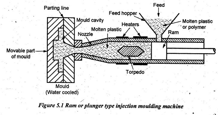
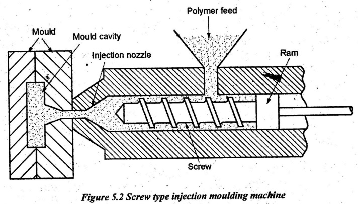
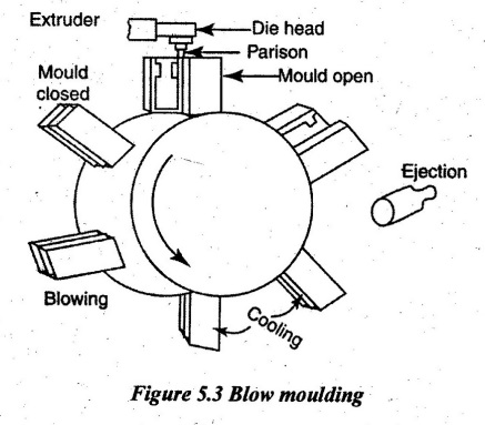
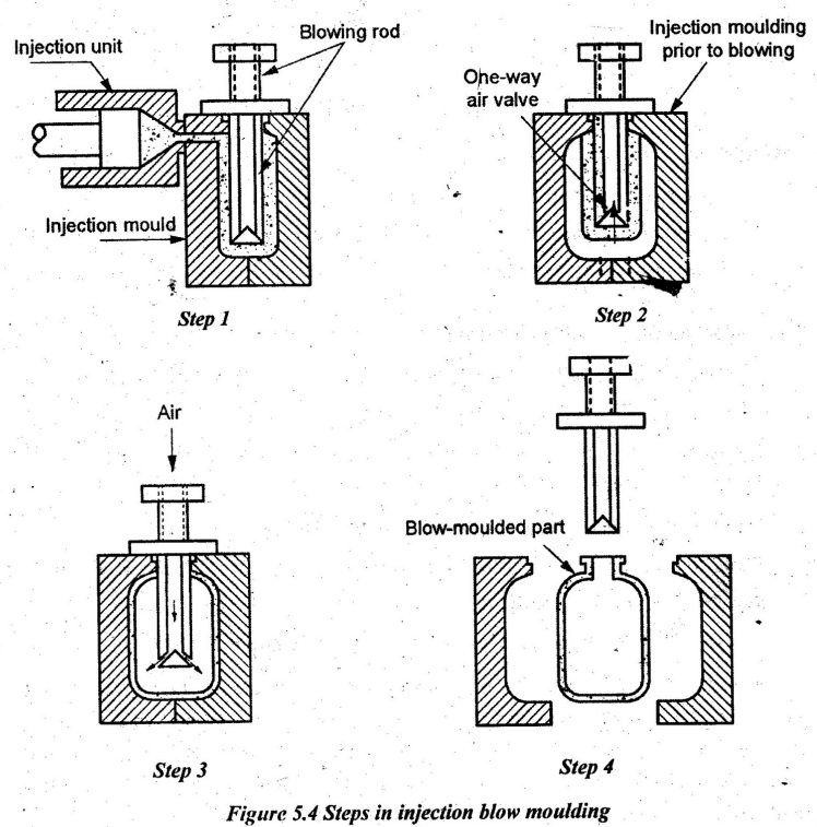
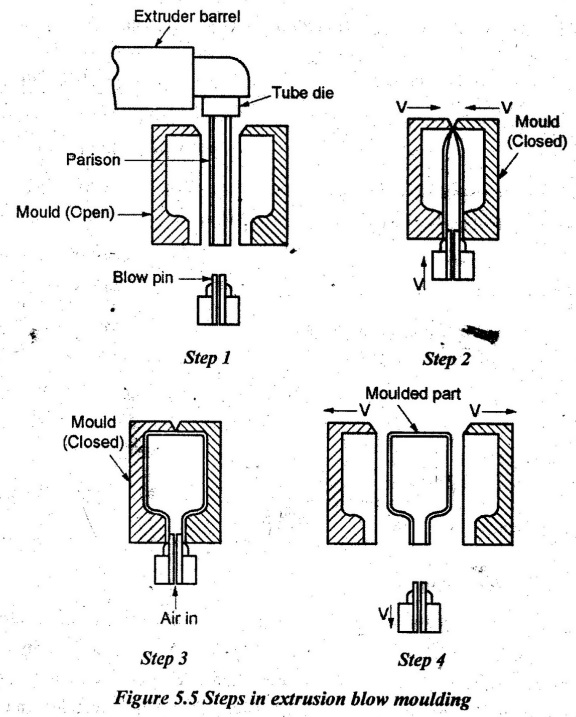
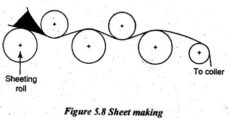
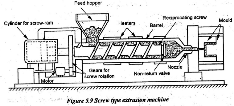
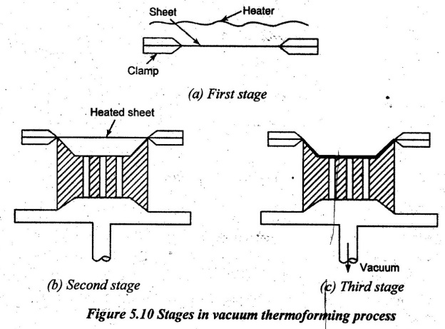
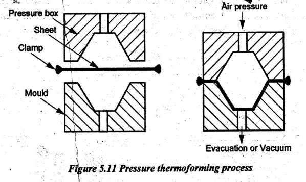
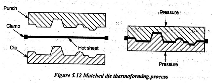
MOULDING OF THERMOPLASTICS AND APPLICATIONS Thermoplastics can be processed to their final shape by moulding and extrusion processes. The various thermoplastics moulding are 1. Injection moulding - Plunger and screw machines 2. Blow moulding 3. Rotational moulding 4. Film blowing 5. Sheet forming process 6. Extrusion process 7. Vacuum forming. The working principles and typical applications of above processes are given below. Working principle: The injection moulding is used to achieve high speed moulding of thermoplastics. The working principle of this process is that the molten thermoplastic is injected into a mould under high pressure. For achieving high pressure, the plunger system is used. Operation: The thermoplastic which is to be moulded is loaded into a hopper. From hopper, it is transferred to a heating section by a feeding device where the temperature is raised to 150°C - 370°C. The thermoplastic melts and transferred to liquid state. It is then forced by an injection ram or plunger through a nozzle and sprue in a closed mould which forms the part. There are two types of injection moulding which are described here. 1. Ram or Plunger Type Injection Moulding A schematic of a typical ram or plunger type injection moulding machine is shown in Figure 5.1. The ram or plunger type injection moulding has the following two units: 1. Injection unit, and 2. Moulding unit. The injection unit is similar to an extruder. It consists of a barrel that is fed from one end by a hopper containing a supply of plastic pellets. Initially, the polymer is filled in a hopper. Then, it is fed to the heating section of the injection unit where the temperature is about 150°C - 370°C. In heating section, the polymer is melted and the pressure is increased. The function of the torpedo in the heating zone is to spread the polymer melt into thin film in close contact with the heated cylinder walls. The fins which keep the torpedo centered also conduct heat from cylinder walls to torpedo. The heated material is injected by the ram under pressure. So, the heated material is forced to fill in the mould cavity through the nozzle to get the required shape of the plastics. Here, the mould is a water-cooled type. The mould is closed during injection by applying a clamping force sufficient to resist the injection force. It must be ensured that the two halves of the mould are in proper alignment with each other before moulding. After completion of injection and cooling of mould, the mould is splitted by moving the movable part of the mould so that the finished component can be ejected. The plunger is then withdrawn, a fresh charge of material drops down, the mould is closed under a locking force and the entire cycle is repeated. 2. Screw Type Injection Moulding In this type also, there are two units to split and eject the finished component such as 1. Injection unit, and 2. Moulding unit. The injection unit has hopper, screw and heating sections. In clamping section, it has mould. In a screw type moulding machine, the pellets are initially fed into the hopper. The resins are pushed along with the heated reciprocating screw. The screw is moved forward to force the plastic material into the mould. The screw itself is moving backward and allowing the accumulation of enough material to fill the mould. The rotation of the screw provides the plasticizing action by shearing and frictional effects. The axial motion of the screw provides the filling action. After completion of injection and cooling of mould, the mould is opened, the part is ejected and removed. The injection capacity of injection moulding machines ranges from 12,000 mm3 to 2.2 × 106 mm3. Advantages of injection moulding: 1. High production capacity and less material losses are possible. 2. The cost is low and it needs less finishing operation. 3. It is used for making complex threads and thin walled parts. 4. Accuracy of ± 0.025 mm can be achieved. 5. Wide range of shapes can be moulded. Limitations of injection moulding: 1. Equipment of cylinder and die should be non-corrosive. 2. The reliable temperature controls are essential. Applications of injection moulding: 1. It is used in making parts of complex threads. 2. Intricate shapes such as thin walled parts can be produced. 3. Typical parts such as cups, containers, tool handles, toys, knobs and plumbing fittings can be produced. 4. Electrical and communication components such as telephone eivers can be produced. 3. Defects in Plastic Injection Moulding Ten common defects that can occur in plastic injection moulding are as follows: (i) Flow lines (ii) Sink marks (iii) Vacuum voids (iv) Surface delamination (v) Weld lines (vi) Short shots (vii) Warping (viii) Burn marks (ix) Jetting (x) Flash 1. Flow lines: Flow lines are streaks, patterns or lines. They are usually off-toned in color which shows up on the prototype part as a consequence of the physical path and cooling profile of the molten plastic as it flows into the injection mould tooling cavity. Injection moulded plastic begins its journey through the part tooling via an entry section called a "gate." It then flows through the tool cavity and cools. Flow line defects are caused by the varying speed at which the molten plastic flows as it changes the direction through the contours and bends inside the mould tool. They also occur when the plastic flows through sections with varying wall thickness or when the injection speed is too low causing the plastic to solidify at different speeds. This problem can be avoided by increasing the injection speed and pressure to the optimal level for checking the cavities whether they are filled properly or not. The temperature of the molten plastic or the mould itself can also be elevated to ensure the plastic does not cool down sufficiently to cause the defect. Round corners and locations should be avoided where the wall thickness changes to avoid sudden changes in the direction and flow rate. The gate is located at a spot in the tool cavity with thin walls. 2. Sink marks: The surface of the moulded product collapses particularly common in thicker products. It is similar to voids but sink marks arise when the surface cools too slowly. It can be avoided by the following ways: (i) By increasing the amount of material feed (ii) By increasing the cavity internal pressure (iii) By lowering the cylinder temperature setting (iv) By increasing the injection rate (v) By increasing the injection speed (vi) By lengthening the injection time (vii) By lowering the mould temperature (viii) By making the mould temperature uniform (ix) By changing the gate locations (x) By making the gates larger (xi) By making the runners shorter (xii) By choosing a highly viscous grade. 3. Vacuum voids: Vacuum voids are pockets of air trapped within or close to the surface of an injection moulded prototype. Vacuum voids are often caused by uneven solidification between surface and inner sections of the prototype. It will aggravate when the holding pressure is insufficient to condense the molten plastic in the mould. Voids can also develop from a part which is cast from a mould with two halves that are not correctly aligned. It can be avoided by the following ways given below: (i) By locating the gate at the thickest part of the moulding (ii) By switching to a less viscous plastic (iii) By increasing holding pressure as well as holding time (iv) By ensuring the alignment of mould parts perfectly. 4. Surface delamination: Surface delamination is a condition where thin surface layers appear on the part due to a contaminant material. These layers appear similar to coatings and can usually be peeled off. Foreign materials find their way into the molten plastic separated from the finished product because the contaminant and the plastic cannot bond. They have not only an effect on the appearance of the prototype but also on its strength. The contaminant acts as a localized fault trapped within the plastic. An over-dependence on mould release agents can also cause the delamination. It can be avoided by the following ways: (i) By pre-drying the plastic properly before moulding (ii) By increasing the mould temperature (iii) By smoothening out the corners and sharp turns in the mould design to avoid sudden changes in melt flow (iv) By focusing more on the ejection mechanism in the mould design to reduce or eliminate the dependence on mould release agents. 5. Weld lines: Weld lines are actually more similar to a plane than a line that appears in a part where molten plastics meet each other as they flow from two different parts of the mould. Weld lines are caused by the inadequate bonding of two or more flow fronts when there is partial solidification of the molten plastic. It can be avoided by the following ways: (i) By raising the temperature of the mould or molten plastic (ii) By increasing the injection speed (iii) By adjusting the design for the flow pattern to be a single source flow (iv) By switching to a less viscous plastic or one with a lower melting temperature. 6. Short shot: The short shots occur where a moulding shot falls short. It means, the molten plastic for some reasons does not fully occupy the mould cavity or cavities thereby resulting in a portion where there is no plastic. The finished product becomes deficient because it is incomplete. Short shots can be caused by a number of things. Incorrect calibration of the shot or plasticizing capacities can result in the plastic material being inadequate to fill the cavities. If the plastic is too viscous, it may solidify before fully occupying all the cavities and result in a short shot. Inadequate degassing or gas venting techniques can also result in short shots that because air is trapped and has no way to escape, plastic material cannot ccupy the space air or gas is already occupying. Short shot can be avoided by the following ways: (i) By selecting a less viscous plastic with higher flowability. This plastic will fill the hardest-to-reach cavities. (ii) By increasing the mould or melt temperature so as to increase flowability (iii) By accounting the gas generation by designing the mould so that gas is not trapped within the mould and it is properly vented (iv) By increasing the material feed in the moulding machine or switching to a machine that has a higher material feed that the maximum material feed has been reached. 7. Warping: Warping (or warpage) is the deformation that occurs when there is uneven shrinkage in the different parts of the moulded component. The result is a twisted, uneven or bent shape where one was not intended. Warping is usually caused by non-uniform cooling of the mould material. Different cooling rates in different parts of the mould cause the plastic to cool differently and thus create internal stresses. These stresses, when released, lead to warping. Warping can be avoided by the following ways: (i) By ensuring the sufficient cooling time and it is slow enough development of residual stresses being locked into the part. (ii) By designing the mould with uniform wall thickness to make the plastic flow in a single direction. (iii) By selecting the plastic materials which are less likely to shrink and deform. Semi-crystalline materials are generally more prone to warping. 8. Burn marks: Burn marks are discolorations. It is usually rust colored which appear on the surface of the injection moulded prototypes. Burn marks are caused either by the degradation of the plastic material due to excessive heating or by injection speeds that are too fast. Burn marks can also be caused by the overheating of trapped air which etches the surface of the moulded part. Burn marks can be avoided by the following ways: (i) By reducing the injection speeds. (ii) By optimizing the gas venting and degassing. (iii) By reducing the mould and melt temperatures. 9. Jetting: Jetting refers to a situation where the molten plastic fails to stick to the mould surface due to the speed of injection. Being fluid, the molten plastic solidifies in a state that shows the wavy folds of the jet stream on the surface of the injection moulded part. Jetting occurs mostly when the melt temperature is too low and the viscosity of the molten plastic becomes too high. It increases the resistance of its flow through the mould. When the plastic comes in contact with the mould walls, it is rapidly cooled and the viscosity is increased. The material flow pushes the viscous plastic further and leaves scrape marks on the surface of the finished product. Jetting can be avoided by the following ways: (i) By increasing the mould and melting temperatures. (ii) By increasing the size of the gate so that the injection speed becomes slower. (iii) By optimizing the gate design to ensure adequate contact between the molten plastic and the mould. 10. Flash: Flash is a moulding defect which occurs when some molten plastic escapes from the mould cavity. Typical routes for escape are through the parting line or ejector pin locations. This extrusion cools and remains attached to the finished product. Flash can occur when the mould is not clamped together with enough clamping force which allows the plastic to seep through. The use of moulds will be worn out and contribute to the possibility of flash. Additionally, excessive injection pressure may force the plastic out through the route of least resistance. Flash can be avoided by the following ways: (i) By increasing the clamp pressure to ensure that the mould parts remain shut during injection. (ii) By ensuring that the mould is properly maintained and cleaned. (iii) By adopting the optimal moulding conditions like injection speed, injection pressure, mould temperature and proper gas venting. Blow moulding is a moulding process in which air pressure is used to inflate soft plastic into a mould cavity. In this process, a hot extruded tube of plastic called parison is placed between two parts of open moulds as shown in Figure 5.3. The two valves of the mould move towards each other so that the mould closes over the tube. The bottom end of the parison is sealed. The compressed air is used to blow the molten plastic into the mould and the tube gets pinched off and also welded at the bottom by closing the moulds. The air pressure is about 0.7 to 10 kg/cm2. This air pressure will force the tube against the walls of the mould. Finally, the component is cooled and the mould is opened to release the components. The blow moulding method ranges from simple manual operation to complicated automatic one. Forming the parison for blow moulding is accomplished by either of two processes: extrusion or injection moulding. Based on the method used for forming the parision, the blow moulding process is classified as follows: 1. Injection blow moulding 2. Extrusion blow moulding. Applications: 1. It is used in making plastic bottles and toys. 2. The hollow containers are produced by this process. 3. The multi-layer blow moulding is used in cosmetics and pharmaceutical industries. In injection blow moulding process, the starting parison is injection moulded. It is used to make seamless bottles without high strength or barrier properties. The sequence of steps in injection blow moulding process is shown in Figure 5.4. The description of these steps is as follows: Step 1: The parison is injection moulded around a blowing rod Step 2: Injection mould is opened and parison is transferred to a blow mould Step 3: Soft polymer is inflated to conform to a blow mould and Step 4: Blow mould is opened and blown product is removed. In another form of injection blow moulding, called injection stretch blow moulding, the blowing rod extends downward into the injection moulded parison during step 2. It stretches the soft plastic biaxially and creats a more favorable stressing of the polymer than conventional injection blow moulding or extrusion blow moulding. It is used for making bottles which require high strength and good barrier properties. When the thermoplast to be moulded is preformed in the same machine which is used for blowing, it is called single-stage machine. Such machines usually have three stations such as injection station, blow station and ejection station. In the conditioning phase, the injection mould is cooled to reduce the viscosity of the material before it moves to the blow mould. These machines are especially slower than the reheat machines because both injection and blowing are done together. If the injection cycle is longer than the blowing cycle, it can slow down the process. There is usually a limit to the number of parts which can be moulded in each cycle. In extrusion blow moulding process, the starting parison is extrusion moulded rather than injection. In most cases, the process is organized as a very high production operation for making plastic bottles. The sequence of steps in extrusion blow moulding process is shown in Figure 5.5. The description of these steps is as follows: Step 1: The parison is extrusion moulded around a tube die Step 2: The parison pinches at the top and seales at the bottom around a metal blow pin as the two halves of the mould come together Step 3: The tube is inflated so that it takes the shape of the mould cavity and Step 4: The mould is opened and the solidified product is removed. The sequence is automated and usually integrated with downstream operations such as bottle filling and labeling. It is usually a requirement that the blown container is rigid and rigidity depends on wall thickness among other factors. The rotational moulding process is used to make thin walled hollow parts. In this moulding, thin walled metal mould is made of two pieces. A measured quantity of powdered plastic material is placed in the mould and the mould is closed. Then the mould is rotated about two mutually perpendicular axes and heated. This action tumbles and sinters the powder against the mould where the heating fuses the powder without melting it. After heating and sintering, the mould is cooled while it is still rotating. The cooling of mould is done by using water and air. Then, the rotation is stopped and the moulded component is removed. Most thermoplastics and some thermosets can be formed into large hollow parts by rotational moulding. In some parts, chemical agents are added to the powder and cross- linking after the part is formed in the mould by continuous heating. Rotational moulding can also produce parts with complex hollow shapes with wall thickness of 0.4 mm minimum. Large size parts as 1.8 m × 1.8 m × 3.6 m can also be formed by this process. The surface finish of the mould is similar to surface finish of walls. The temperature-time relationship during the oven cycle is very important. Applications of rotational moulding: 1. It is used to produce toys using PVC. 2. It is used to make large containers of polyethylene. 3. It is used to make petrol tanks for motorcars from polyethylene and nylon. 4. Metallic or plastic inserts are moulded by this process. 5. The buckets, housings, boat hulls and trashcans are made by this process. 6. It is used to produce tanks of various sizes, boat hulls and footballs. One of the most widely used methods of film forming is film blowing. Crystalline sharp melting polymers such as nylon or polyethylene terephthalate (PET) are very much suited for the film productions by melt casting techniques. Initially, the heated plastic powder is extruded by using extrude machines called extruder. The equipment used in-film blowing is shown in Figure 5.7. Air is introduced through a hole at the center of the die to blow up the tube similar to a balloon. The die is similar to die used for making pipes or tubings. A high speed air ring mounted at the top of the die blows into the hot film to cool it. The collapsing frame takes the bubble and collapses the tubular film before it is pulled through the nip rolls. Since the film is drawn upward and expanded radially by air pressure, a biaxially oriented film is produced. Most plastic bags and wrapping films are made in this way. The liquid polymer is forced upward through the spin annular slit, emerging into the atmosphere as a thin-walled continuous tube. The tube is then very rapidly dragged upwards by the pull rolls and expanded by internal pressure. At the same time, the cooling air jets are used to solidify at some tens of centimeters above the shaper lips. The bubble is collapsed and the film is rolled onto a wind-up roll. The stability of the bubble is crucial Applications of film blowing: Blown film can be used either in a tube form (e.g. for plastic bags and sacks) or the tube can be slit to form a sheet. Typical applications include the following areas: 1. Industry packaging (e.g. shrink film, stretch film, bag film or container liners) 2. Consumer packaging (e.g. packaging film for frozen products, shrink film for transport packaging, food wrap film, packaging bags or form, fill and seal packaging film) 3. Laminating film (e.g. laminating of aluminium or paper used for packaging for example milk or coffee) 4. Barrier film (e.g. film made of raw materials such as polyamides and Ethylene-Vinyl Alcohol Copolymer (EVOH) acting as an aroma or oxygen barrier used for packaging food such as cold meats and cheese). Calendering process is used for sheet making. A calender is a series of hard pressure rollers used to form or smooth a sheet of material such as paper or plastic film. In this process, the plastic compounds composed of resin, filles, plasticizer and other additives are heated for sometime and passed through the heated rollers. It is similar to the rolling process in which the material is compressed and emerged as a sheet. The thickness of the sheet is controlled by a combination of squeezing and altering the speed of rolls. The finishing thickness is determined by setting gap between rolls at the final stage. In this rolling process, the first roll gap serves as a feeder, the second one as a metering device and the third roll gap sets the gauge for the gradual cooling plastic which then wound in a coiler. Applications: 1. It is used for making PVC, tapes, and rainwear with very high production rate. 2. It is also used for making floor tiles and cellulose acetate sheets. The extruder is the main device used to melt and pump thermoplastics through a shaping device called a die. Figure 5.9 shows the screw type extrusion machine. The process consists of feeding the powdered plastic from the hopper into the heating chamber. In this extruder, one screw rotates within a metallic barrel: The screw imparts both axial and rotary motions. The rotating screw carries the material forward and forces it out through the heated orifice to the die. The restricting effect of the die will build up a pressure until it is in a plastic state and it can be extruded. The required shape is obtained through the die. The raw material is in the form of pellets, granules and powder. The thermosetting plastics are not suitable for extrusion. For the extrusion of plastics, a single screw machine has completely replaced the ram type machine. The screw has three distinct sections. 1. Feed section connects the material from hopper into the central region of the barrel. 2. Melt section in which plastic starts to melt. 3. Pumping section in which additional shearing and melting occur. Applications: 1. It is used to make tubes, sheets, films, pipes, ropes and other profiles. 2. Complete shapes with constant cross sections can be extruded with relatively inexpensive tooling. 3. Plastic extruders are also extensively used to reprocess the recycled plastic waste or other raw materials after cleaning, sorting and/or blending. Thermoforming is the process in which the thermoplastic sheets are formed with the application of heat and pressure in a mould. Thin sheet (up to 1.5 mm) and thick sheet (about 3 mm) can be formed easily. This process involves the following steps: ● The thermoplastic sheet is heated to a predetermined temperature range. ● The heated and softened plastic sheet is pressed into or stretched over the mould surface by the application of air pressure or vacuum or any other means. ● The softened sheet conforms to the mould shape and it is held in place until it cools. ● The formed part is removed from the mould and excess plastic is trimmed. ● The following three methods of thermoforming processes are generally used: ● Vacuum forming ● Pressure forming ● Matched die forming. (a) Vacuum forming: In this process, the vacuum pressure is used to form the heated thermoplastic sheet into the desired shape. Figure 5.10 shows the vacuum forming process in which the plastic sheet is heated in a heater and the sheet is fixed in a clamp in the first stage. In the second stage, the heated sheet is placed on the die where the air between sheet and mould is removed.. In the third stage, increasing the intensity of vacuum draws the sheet against the surface of the mould where it cools and solidifies. Then, the thermoformed part is ejected from the mould cavity. If large surface area moulds are used, it will be difficult to stretch the plastic into the mould. In this case, the mechanical assist is given to stretch the plastic into the mould. (b) Pressure forming: The pressure forming process is similar to vacuum forming process. In this process, the air pressure required is much higher as compared to the vacuum forming. The preheated plastic sheet is placed on the mould surface. Then, the air pressure is applied quickly above the sheet as shown in Figure 5.11. The high pressure is developed in between the softened sheet and the pressure box. Due to high pressure, the preheated plastic sheet can be deformed into the mould cavity ́in a fraction of a second. The formed sheet is held in the mould cavity for cooling for a few seconds. The formed part thereby solidifies and is ejected from mould cavity. (c) Matched die forming: This method is also called mechanical forming. In this process, mould consists of two parts i.e. die and punch as shown in Figure 5.12. The thermoplastic sheet is heated with the application of heat until it softens. The preheated sheet is placed into the die surface and through punch pressure is applied on the hot sheet. The air in between die and softened sheet is evacuated by using vacuum pump. Therefore, the thermoplastic sheet is formed to the mould shape. The formed part is cooled and ejected from the mould cavity. Advantages of thermoforming: 1. It is extremely adaptive to design requirement. 2. It is useful for rapid prototype development. 3. Initial setup cost is low. 4. Production cost is low. 5. There are less thermal stresses than injection moulding and compression moulding. 6. Dimensional stability is good. Disadvantages of thermoforming: 1. Surface finish is poor. 2. Parts may have non-uniform wall thickness. 3. All parts need to be trimmed. 4. Ribs and bosses cannot be moulded easily. 5. Limited number of materials can be used. 6. Very thick plastic sheets cannot be formed. Applications of thermoforming: 1. It is very much useful for making trays, drink cups and refrigeration door lines. 2. It is used for making panels for shower stalls and advertising signs. 3. Thin gauge parts made using thermoforming are primarily used to package or contain a food item, disposable cups, containers, lids, blisters and clamshells. 4. This process is used to make heavy gauge products such as signs and thin gauge product such as picnic plates.1. Injection Moulding
2. Blow Moulding
3. Injection Blow Moulding Process
4. Extrusion Blow Moulding Process
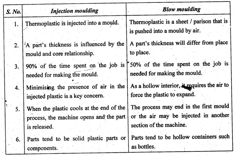
5. Difference between Injection Moulding and Blow Moulding
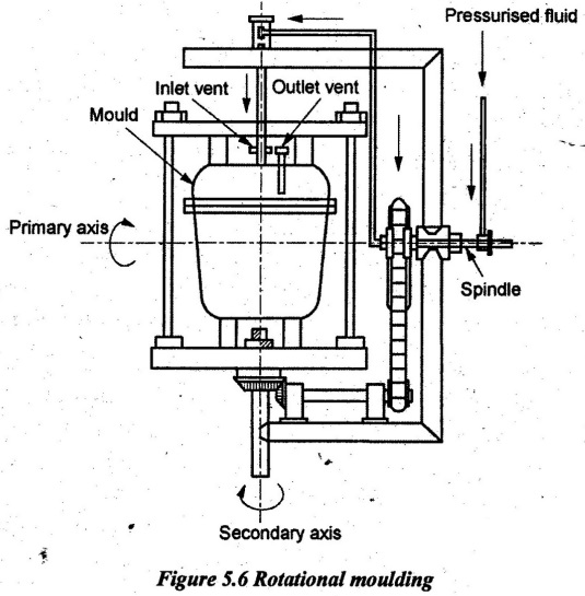
6. Rotational Moulding
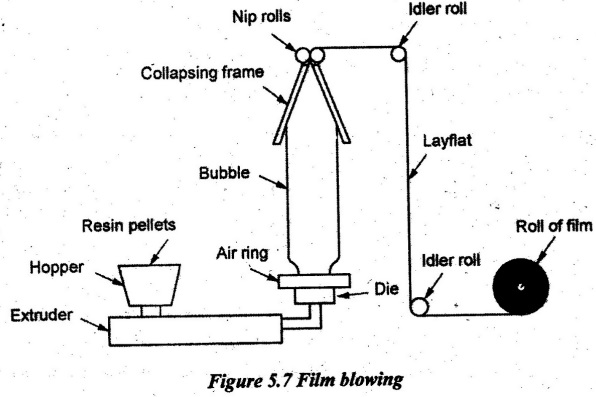
7. Film Blowing
8. Sheet Making
9. Extrusion Process
10. Thermoforming
Manufacturing Processes: Unit V: Manufacture of Plastic Components : Tag: : Working Principle, Operations, Advantages, Disadvantages, Applications - Moulding of Thermoplastics and Applications
Related Topics
Related Subjects
Manufacturing Processes
ME3393 3rd semester Mechanical Dept | 2021 Regulation | 3rd Semester Mechanical Dept 2021 Regulation