Manufacturing Technology: Unit III: Reciprocating Machine Tools
Milling Machine
Reciprocating Machine Tools - Manufacturing Technology
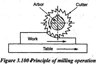
Milling is the process of removing metal by feeding the workpiece against a rotating multipoint cutter.
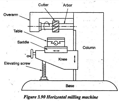
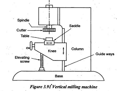
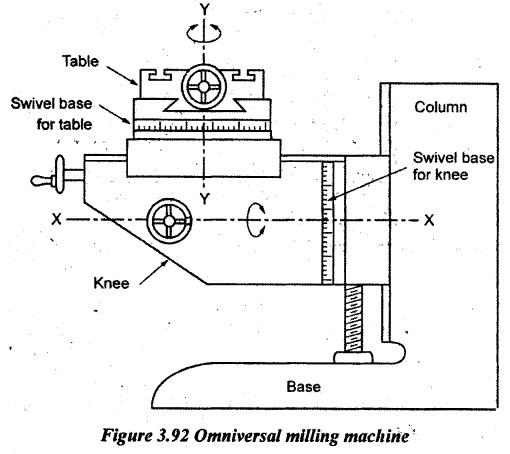
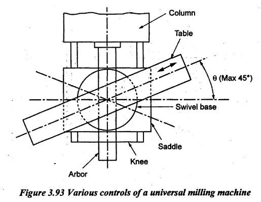
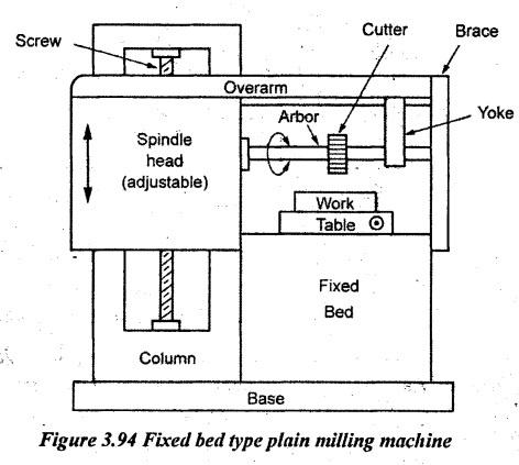
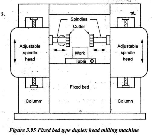
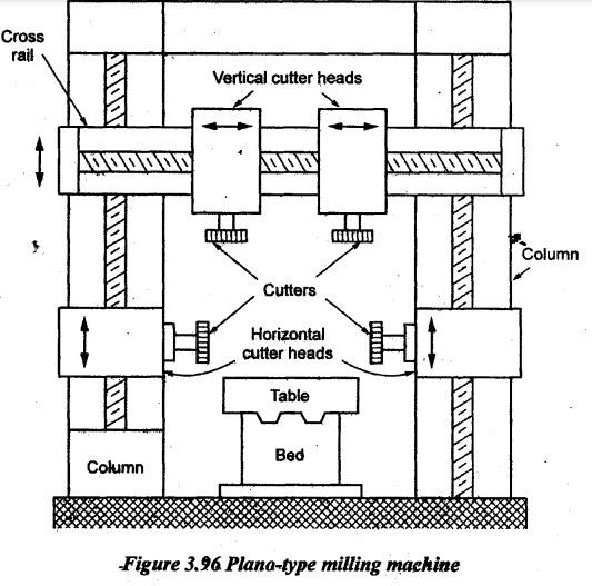
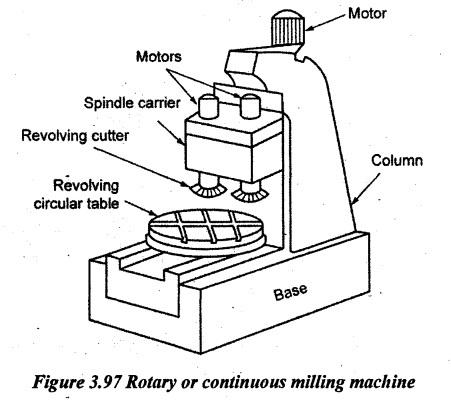
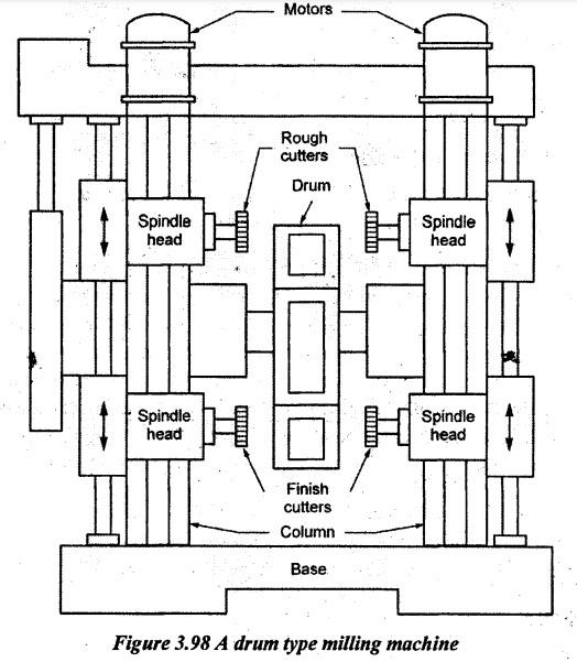
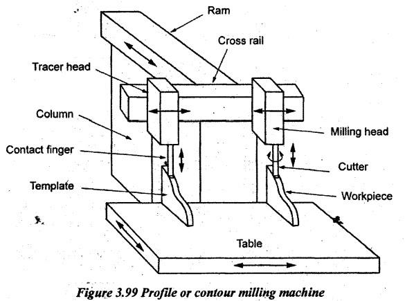
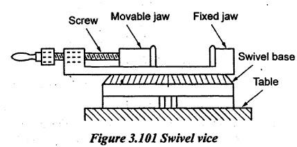
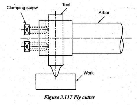
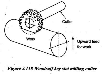
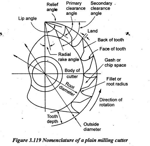
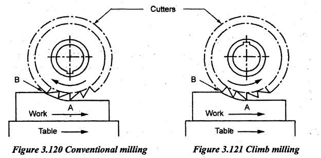
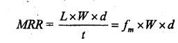
MILLING MACHINE Milling is the process of removing metal by feeding the workpiece against a rotating multipoint cutter. The metal is removed in the form of small chips. In the milling operation, the ratio of metal removal is rapid as the cutter rotates at a high speed and it has many cutting edges. Thus, the jobs are machined at a faster rate than single point tools and the surface finish is also better due to multiple cutting edges. Milling machines are used for machining flat and irregular surfaces. Milling machine are classified in many ways. The broad classification of these machines can be done as follows. 1. Column and knee type milling machine a) Plain milling machine b) Vertical milling machine c) Universal milling machine d) Ram-type milling machine e) Omniversal milling machine. 2. Bed-Type milling machine a) Simplex milling machine b) Duplex milling machine c) Triplex milling machine. 3. Plano-type milling machine 4. Special purpose milling machines a) Rotary table milling machine b) Drum milling machine c) Profile milling machine. 1. Column and Knee Type Milling Machines Column and knee type milling machines are most commonly used for general shop floor works, maintenance work, tool room work, etc. It has a vertical column on its base. The column has machined guide ways on its front face. A knee slides up and down on these ways. The column serves as a housing unit for speed and feed mechanisms. The knee carries the saddle and worktable. There are two types of column and knee type milling machines. (i) Horizontal type (ii) Vertical type. In a horizontal type milling machine, the axis of rotation of arbor is horizontal. In a vertical type milling machine, the axis of rotation of arbor is vertical. 1. Plain or horizontal milling machine: It is a horizontal column and knee type milling machine, otherwise, simply a horizontal milling machine. A description of the principle parts of a milling machine is as follows. (i) Base: It is the foundation of the machine made of grey cast iron. All other parts are mounted on it. It also serves as a reservoir for cutting fluid. (ii) Column: It is the main support of the machine. The motor and other driving mechanisms are housed in it. It supports and guides the knee in its vertical travel. (iii) Knee: The knee projects from the column and slides up and down through dovetail guides. It supports saddle and the table. An elevating screw provides its vertical movement (up and down). (iv) Saddle: The saddle supports and it carries the table. It provides the traversed movement. (v) Table: The top surface of the table is accurately machined. There are T-slots along the length of the table for holding the work. The table rests on the guide ways of the saddle and longitudinally travels in a horizontal plane. It supports the workpiece, fixtures etc. (vi) Overarm: It is mounted and guided by the top of the column. The overarm is used to hold the outer end of the arbor to prevent it from bending. (vii) Arbor: Arbor is an accurately machined shaft. Cutters are mounted on the arbor which is rigidly supported by the over arm, spindle and end braces. It is tapered at one end to fit the spindle nose and it has two slots to fit the nose keys for locating and driving it. 2. Vertical milling machine: A vertical milling machine can be distinguished from a horizontal milling machine by the position of its spindle which is vertical or perpendicular to the worktable. It carries a vertical column on its heavy base. The spindle head which is clamped to the vertical column may be swiveled at an angle permitting to work on angular surfaces. The over arm in this machine is made integral with the column and it carries a housing at its front. The machine is used for machining grooves, slots and flat surfaces. Generally, the vertical milling machine is used to perform end milling and face milling operations. Figure 3.91 illustrates the vertical milling machine. The knee carries an enclosed screw jack by means of which it is moved up and down along the parallel vertical guide ways provided on the front side of the column. The saddle is mounted on the knee and it can be moved along the horizontal guide ways provided on the knee towards or away from the column. It enables the table to move in the cross direction. The table is mounted on guide ways provided on the saddle which is in a direction normal to the direction of the guide ways on the knee. By means of a lead screw provided under the table, the table can be moved in the longitudinal direction. Thus, the work gets up and down movement by the knee, cross movement by the saddle and longitudinal movement by the table. Power feeds can be employed to both the saddle and the table. Mostly, the face milling cutters and shell-end type cutters are used on these machines. 3. Omniversal milling machine: It is a modified form of a plain (horizontal) milling machine. It is provided with two swivel bases, one of which is in the horizontal plane while the other one is carried by a universal swiveling head. The latter can be fixed in vertical position or can be set at any desired angle up to 90° on both sides of the vertical plane. The knee of this machine can also be swiveled in the horizontal plane. Thus, it enables to carry out a large number of operations such as spiral grooves in reamers, bevel gears etc. Figure 3.92 shows this type of machine. 4. Universal milling machine: It is the most versatile of all milling machines with its applications. The use of a large number of other machine tools can be avoided if it is used. In appearance, a universal milling machine is similar to a horizontal milling machine. The worktable of this machine is provided with another extra swivel movement with an index or dividing head located at the end of the table. Thus, the universal milling machine table has the following movements. 1. Vertical movement - through the knee 2. Crosswise movement - through the saddle 3. Longitudinal movement of the table 4. Angular movement of the table by swiveling the table on the swivel base. The swiveling attachments provided on these machines help in cutting spirals, gears and cams in addition to normal milling operations. These machines are very accurate and used mainly for tool room work. The various controls of a universal milling machine are shown in Figure 3.93. Comparison between plain and universal milling machine: 1. In a plain milling machine, the table is provided with three movements such as longitudinal, cross and vertical. In universal milling machines. There is a fourth movement to the table in addition to these three movements. The table can horizontally be swiveled and it can be fed to the required angle to the milling machine spindle. 2. The universal milling machine is provided with auxiliaries such as dividing head, vertical milling attachment, rotary table etc. Hence, it is possible to make the spiral bevel gears, twist drills, reamers etc. on the universal milling machine. 3. The plain milling machine is more rigid and heavier in construction than a universal milling machine. 4. The plain milling machine is used for general manufacturing operations whereas the universal milling machine is used for tool room work and special machining operations. 2. Bed Type Milling Machines These are comparatively large, heavy and rigid in construction. The vertical motion is imparted to the spindle head instead of the table. Depending upon the number of spindles, these are classified as simplex, duplex and triplex machines. 1. Fixed bed type simplex milling machine: In a fixed bed plain milling machine, the table is mounted on a fixed bed instead of a saddle and knee as in the case of a plain milling machine. Since the bed is fixed, it cannot move up, down or crosswise direction. The machine consists of an adjustable spindle head and spindle carrier fixed rigidly to the column with parallel vertical ways. The spindle head - carries the spindles which can be moved up and down along the column ways to adjust the tool in the proper position for carrying out different milling operations. 2. Duplex head fixed bed type milling machine: It is another useful form of the fixed bed type milling machine. In appearance, it is similar to the fixed bed type simplex milling machine except carrying two vertical columns instead of one. The columns are one each on both sides of the fixed bed as shown in Figure 3.95. Both columns 'carry parallel vertical ways on which two adjustable spindle heads or spindle carriers are mounted. Both carriers carry a horizontal spindle each on which cutters can be mounted. The spindle carriers can vertically be adjusted up and down to adjust the cutters to the work. The table has only longitudinal movement and it cannot be moved in any other directions. This machine enables simultaneously machining the two surfaces. 3. Triplex-head fixed bed type milling machine: It is similar in construction and operation to the duplex head milling machine described above. The only difference lies in the number of spindles. It carries in addition to the two horizontal spindles, one vertical spindle also. Thus, three surfaces can simultaneously be machined on this type of machine. 3. Plano-Type Milling Machine It is similar in appearance and construction to a double housing planer. The working - principle is also similar to the planing machine. The essential difference between planer and Plano-miller lies in the table movement. In a planer, the table moves to give the cutting speed but in Plano-miller, the table movement gives the feed. Hence, the table movement in Plano- miller is much slower than in a planer. The line diagram of Plano-miller is shown in Figure 3.96. The machine has a fixed bed. The bed has longitudinal guide ways. The table longitudinally reciprocates over these guide ways. There are two vertical columns each provided on each side of the bed. There are two cutter heads mounted on the vertical columns. They can slide over vertical guide ways on the column. A cross rail vertically slides along the column guide ways. The cross rail carries vertical cutter heads. These cutter heads can slide along the cross rail. The work can be machined in four different ways according to requirements as follows. 1. By moving the table and rotating the cutters in position. 2. By keeping the table stationary and feeding the cutters by moving the milling heads. 3. By moving the table and the milling heads simultaneously. 4. By keeping the table stationary and moving the cross-rail downwards and also the side cutters up and down. All four cutter heads can be used to machine the work surfaces at a time. The cutter heads can also be swiveled for machining angular surfaces. This machine is used for heavy duty production work such as lathe bed ways, other machine bed ways etc. 4. Special Purpose Milling Machines These machines are designed to perform only a specific type of operations. The various special purpose milling machines are described below. 1. Rotary table or continuous milling machine: It is largely used in mass production of machining components through milling. Its construction is heavy and robust. The special feature of this machine is that the process of machining is continuous and there is no idle machining time. It is the modification made to a vertical milling machine. It consists of two vertical spindles mounted with face milling cutters. A number of workpieces are clamped on a circular table which rotates about a vertical axis. The cutters may be set at different heights relative from work so that when one of the cutters is for roughing operation and the is for finishing operation. 2. Drum type milling machine: It is another heavy-duty production machine in which two end faces of the workpieces are simultaneously machined. It consists of two vertical columns mounted on a sturdy base. The milling heads are mounted on two columns. These heads carry horizontal spindles and they can be adjusted in a vertical direction along the column. A typical design carrying 4 spindles is shown in Figure 3.98. Cutters mounted on these spindles are face mills. The upper two spindles carry roughing cutters and the lower spindles carry two finishing cutters. A heavy drum is centrally mounted between columns which rotate about a horizontal axis. The well-designed fixtures are mounted along the periphery of the drum to carry the jobs to be machined. The drum continuously rotates and the workpieces are mounted on fixtures on the rear side of the machine. They first come in contact with the upper cutters in which rough machining takes place on faces and then with the lower cutters which provide the finishing cuts. They are unloaded and replaced by new jobs again on the rear end of the machine. 3. Profile or contour milling machines It has a cutter guided by means of a guide pin which is held against it and it follows the outline of the profile on a guide block or template. Its table can simultaneously give both longitudinal and cross feeds or independently as desired. The simultaneous feeding enables the diagonal motion. A template which is the replica of the shape to be produced is fitted to the machine. The contact finger or hydraulic tracer unit or tracer head makes a light contact with contours of the template and guides the cutter movement, synchronizing with the table movement, to produce a similar machined surface as on the template. A typical milling machine is specified by the following parameters: 1. The table length and width 2. Maximum longitudinal cross and vertical travel of the table 3. Number of spindle speeds and feeds 4. Power of driving motor 5. Floor space and net weight 6. Spindle nose taper size 7. Type of milling machine. The action of a milling cutter is vastly different forms from drill or lathe tool. The milling machine has a rotating cutter. The multipoint cutter is mounted on a rotating spindle or arbor. The cutter rotates at the required cutting speed. The workpiece is clamped on the table. The workpiece is slowly fed past the cutter. As the work advances, the metal is removed by cutting edges in the form of chips. The feed may be longitudinal, crosswise or vertical in nature. The angular feed can also be given in certain milling machines. During machining, when one cutting edge performs the cutting, the other edges will be idle. So, these edges are cooled. Also, the stress on the cutting edge is not continuous. It gives more life to the cutting edge. Figure 3.100 illustrates the principle of operation of the milling process. The milling machine drive mechanism includes a main shaft, a gear assembly and a machine shaft. The gear assembly includes a first gear and a second gear. The first gear is pin-jointed to the main shaft to rotate with the main shaft. The second gear is operatively connected to the first gear but the main shaft drives the second gear to rotate through the first gear. The main shaft is pin-jointed to the main shaft to rotate with the second gear. It is elaborately explained in indexing methods. The following work holding devices are used for clamping the work in the milling machine. (a) 'T bolts and clamps (b) Angle plates (c) 'V' blocks (d) Machine vices (e) Milling fixture (f) Dividing heads. Clamping the workpiece by using 'T' bolts and clamps, angle plate and 'V’ block is similar to the methods already explained in the shaper. The other methods of work holding are explained here. 1. Swivel vice: This vice has a circular base graduated in degrees. The base is clamped on the table by using 'T' bolts. The vice can be swiveled over the swivel base about the vertical axis after loosening the clamping bolt. After setting the vice to the required angle, the clamping bolts are tightened. 2. Universal vice: The universal vice can be tilted in a horizontal and vertical plane. There is a horizontal swivel base on the base of the vice which is used for tilting the vice in a horizontal plane. Over the horizontal swivel base, a vertical swivel arrangement is provided. It is used to tilt the vice body to a certain degree. This vice is not rigid in construction. It is mainly used in tool room works. 3. Indexing or dividing head: It is a device used for dividing the periphery of the workpieces into any number of equal divisions. The process of dividing the periphery of work is called indexing. Indexing is essential for cutting gears, splines, equally spaced grooves, hexagonal heads etc. The indexing head has a headstock and tailstock. The workpiece is held between centers of headstock and tailstock. The short workpieces are held in a chuck fitted to the headstock spindle. The workpiece can be indexed by rotating the crank in the headstock. The crank movement is transmitted to the workpiece through a worm and worm wheel. The indexing plate is used to rotate the crank to a required angle. 4. Milling fixture: The milling fixtures are used when the aforementioned holding devices are not suitable for production work, mass production and for accurate location of jobs. These are especially useful when a large number of identical parts are to be produced. The use of fixtures minimizes loading, locating, clamping and unloading time. Depending on the design requirement, the different types of milling fixtures are used on machines. Depending on the design of the cutter, the following cutter holding devices are used on milling machines. 1. Arbors 2. Adapters 3. Collets. 1. Arbors: There are two types of arbors used in milling machines. (i) Standard arbor (ii) Stub arbor. (i) Standard arbor: Cutters having a central bore are mounted on the standard arbor of a milling mach It is a long slender shaft. It has a taper shank at one end. The shank has internal threads. Araw bolt holds the arbor in a position. The draw bolt is introduced into the spindle bore from the back of the milling machine column. The draw bolt is screwed into the threaded hole of the arbor. The draw bolt is used to pull in or push out the arbor from the spindle. The slots on the flange of the arbor engage the driving lugs of the spindle. A key runs for the whole length of the arbor. It is to fix the cutter and to get a positive drive on the cutter. The arbors are provided with a set of spacing collars. The spacing collars are used to set the cutter in the required position. The arbor is supported at the other end by the yoke of the milling machine. The yoke can be adjusted on the over arm. At the end of the arbor, a bearing bush is inserted. It rests on the yoke. (ii) Stub arbors: It is a short arbor. Its construction is similar to a standard arbor. But it has a short shaft to hold the cutter. Its taper shank fits into the taper hole of the spindle. The draw bolts are used to pull the arbor tightly and hold the arbor in position. The flange of the arbor is clamped to the spindle nose to give a positive drive. One or two spacing collars are used to set the cutter in position. A clamping screw may be used to fit the cutter in the arbor when face and side milling cutters are used. 2. Adapter: many cutters have tapered shank. If the size of the shank is smaller than that the hole in the spindle nose, adapters are used to hold these cutters. It has an internal taper hole to receive the taper shank of the cutter.It has an external taper corresponding to the spindle nose hole taper. The flange of an adapter is made to have two slots to engage the driving dogs of the spindle. The rear end of the adapter carries internal threads to engage the threaded front end of the drawbar. It is held in the spindle in the same way as the arbor. 3. Spring collet: Milling cutters which carry straight shanks held in a collet chuck carrying a spring collet. Figure 3.107 illustrates the construction of a spring collet and collet chuck. The collet chuck has a taper shank to fit into the milling machine spindle. It has internal threads for tightening it with the spindle by means of a draw bolt. It has an externally threaded body. The body has a tapered hole to receive the collet. The tapered portion of the spring collet is split into three equally spaced slots. The collet has a cylindrical hole to receive the straight shank of the cutter. A special nut fits over the taper of the collet and the threaded portion of the chuck. When this nut is tightened, the split jaws of the collet close over the straight shank of the cutter. Thus, the tool is held firmly on the collet. Many standard or special auxiliary devices are used in a milling machine for augmenting the range, versatility, productivity and accuracy of operation. Some milling attachments are used for positioning and driving the cutter by altering the axis of rotation. Other devices are used for positioning, holding and feeding the work. The various attachments used on milling machines are given below. (a) Vertical milling attachment: It is an attachment used for converting a horizontal milling machine into a vertical milling machine by orienting the cutting spindle axis from the horizontal to the vertical position. A vertical milling attachment is used for vertical milling operations with large end mills and face mills. The spindle head can be swiveled to any degree for milling operations. (b) Universal milling attachment: The spindle of a universal milling attachment can be swiveled about two mutually perpendicular axes and sets at any angle in both planes. In other aspects, it is similar to a vertical milling attachment. This attachment is especially useful when the spindle needs to be set at an angle to the table for angular milling. (c) High speed milling attachment: A high speed milling attachment consists primarily of a number of gears (4 to 6) enclosed in a casing for increasing the normal speed of the milling machine spindle. It is used to obtain the correct cutter speed for small milling cutters. (d) Rotary attachment: A rotary attachment is also known as circular milling attachment. It is used for a variety of circular milling operations such as segment outlines, spline slotting segmental milling and die making jobs. The attachment consists of a rotary table which is mounted at the top of the machine table and it provides rotary motion to workpiece. The circular table may be rotated by hand or with the help of power by linking the rotary table mechanism with the lead screw. The circumference of the table is graduated in degrees for accurate work. (e) Slotting attachment: The slotting attachment consists of a tool slide and an eccentric or crank housed within the attachment. It converts rotary motion into reciprocating motion making the machine operate such as a slotter. It is largely used for making tools, keyways and splines. The attachment can be set at any angle from 0 to 90°. (f) Rack milling attachment: The attachment consists of a gear train and enables the spindle axis to be oriented at right angles to the machine spindle. It is used for cutting rack teeth but it can also be used in conjunction with the universal spiral index for cutting worms and other miscellaneous operations. (g) Universal spiral milling attachment: It is a device used principally for milling helical and spiral gear teeth. The attachment is used on a plain or universal milling machine by bolting on the face of the column. It is suitable for vertical and angular milling operations for cutting worms and grooves on milling cutters and twist drills. These are multi tooth rotary cutting tools generally made of high speed steels or sintered carbides. Milling cutters are classified into different ways. (i) According to the shape of the tooth (a) Milled tooth cutters (b) Form relieved cutters. (ii) According to the type of operation (a) Plain milling cutters (b) Side milling cutters (c) End mill cutters (d) Angle milling cutters (e) T-slot milling cutters (f) Slitting saws (g) Form milling cutters (h) Fly cutters (i) Wood ruff key slot milling cutter. (iii) According to the way of mounting on the machine (a) Arbor cutters (b) Shank cutters (c) Face cutters. 1. Elements of Plain Milling Cutters It is also known as a mill cutter. It is a disc or cylindrical shaped cutter having teeth on its circumference. It is used to machine the flat surface parallel to its axis. There are two types of plain milling cutters commonly used. (i) Plain straight teeth cutter (ii) Plain milling helical teeth cutter. Straight teeth plain milling cutters are used for light operations. Helical teeth cutters are used for heavy cut operations. Cutters of various diameters and widths are available. Roughing cutters will have less number of teeth. Finishing cutters will have more number of teeth for the same diameter. The plain milling cutters having the width more than its diameter as shown in Figure 3.108 is called slab mill cutter. It is used for rough machining with coarse feed. The cutter has less number of teeth. 2. Side Milling Cutters It has cutting edges on its periphery and also on sides. This cutter is used for removing metal from the side of the workpieces. It is also used for cutting slots. These cutters may have plain, helical or staggered teeth. Among these three, helical cutters are preferred on milling machines since they require less power for machining. Also, it provides smoother operation as more than one tooth performed a milling operation at a time. 3. End Milling Cutters The end milling cutters have cutting teeth on the end as well as on the periphery of the cutter as shown in Figure 3.111. The peripheral teeth may be straight or helical. It is similar in construction to a twist drill or reamer. These cutters are generally provided with a shank on one end. The shank may be of straight or tapered. Tapered shank cutters are fitted to the spindle using adapters. Straight shank cutters are fitted to the spindle using collets. End mills are commonly used for vertical milling operations. They are used for light milling operations such as cutting slots, machining accurate holes and profile milling. 4. Angle Milling Cutters All cutters which have their cutting teeth at an angle to the axis of rotation are known as angular cutters. Their specific uses are in milling V-grooves, notches, dovetail slots, reamer teeth and other angular surfaces. Angular cutters are classified into single angle cutters and double angle cutters. A single angle cutter may have their teeth either only on the angular face or on both, angular face and side as shown in Figure 3.112. The latter type enables simultaneously milling both the flanks of the inclined angular groove. Their teeth may have an included angle of 45° to 60°. Double angle cutters differ from single angle cutters in such a way that they have two angular faces which join together to form V-shaped tooth as shown in Figure 3.113. The included angle of this 'V' is either 45°, 60° or 90°. The angle of both sides should be equal. 5. T-slot milling Cutters It is a single operation cutter which is used only for cutting T-slots. The arrangement of cutting teeth is similar to a side milling cutter. But this cutter has a tapered shank. A neck is formed between cutting face and shank as shown in Figure 3.114. The cutter has cutting edges on its periphery and sides as mentioned A, B and C in Figure 3.114. 6. Slitting Saws These are very thin cutters in varying thickness from 0.5 mm to 5mm. They are used for cutting deep slots and parting off materials into pieces. These cutters are thinner at the centre than edges to provide clearance and reduce friction. 7. Form Milling Cutters The cutters which are designed to cut definite shapes are known as form milling cutters. These cutters can be classified according to their shape as convex or concave cutters, gear cutters, flute cutters and corner rounding cutters. Convex milling cutter has teeth curved outward on its periphery as shown in Figure 3.116 (a). The cutter will produce a concave semi-circular surface on the workpiece. Concave milling cutter has teeth curved inwards on its periphery as shown in Figure 3.116 (b). The cutter will produce a convex semicircular surface on the workpiece. Gear cutters have formed cutting edges. The shape of the cutter teeth is involute. The cutter will produce groove of involute shape. The involute gear tooth is formed between two grooves milled by the cutter. The profile of the gear tooth depends upon the module and the number of teeth on the gears. Therefore, for cutting different number of gear teeth with the same module, different cutters are required. The corner rounding cutters are used for milling the edges and corners of the jobs to a required radius. 8. Fly Cutters It is actually a single point tool which is used in milling machine when standard cutters are not available. It is either mounted on a cylindrical body held in a stub arbor or held in a bar. Clamping screws are used for tightly holding the tool in above holders as shown in Figure 3.117. The cutting edge of the tool is ground to the required shape. The cutter removes metal when it rotates. 9. Woodruff Key Slot Milling Cutter It is a small type of end milling cutter which is similar to plain and side mills. It has a taper shank and neck. The cutter may have straight or staggered teeth. The sides of the cutter are ground concave as shown in Figure 3.118. It provides a clearance for the cutter movement. It is used to cut woodruff key slot in a shaft. Figure 3.119 shows the principle parts and angles of a plain milling cutter. The various elements of a plain milling cutter are as follows. 1. Body of cutter: The main frame of the cutter on which the teeth rest to form an integral part is known as body of the cutter. 2. Cutting edge: The edge formed by the intersection of teeth and the circular land of the surface left by the provision of primary clearance is known as cutting edge. 3. Face: The portion of the gash adjacent to the cutting edge on which the chip impinges as it is cut from the work. 4. Fillet: Fillet is the curved surface at the bottom of gash which joins the face of one tooth to the back of the tooth immediately ahead. 5. Gash or chip space: The chip space between the back of one tooth and face of the next tooth is called gash. 6. Lead: The cutter advances the distance in one complete revolution or turn. 7. Land: The part of the back of tooth adjacent to the cutting edge which is relieved to avoid interference between the surface being machined and the cutter is called land. 8. Outside diameter: The diameter of the circle passing through the peripheral cutting edge is called outside diameter. 9. Root diameter: The diameter of the circle passing through the bottom of the fillet is called root diameter. 10. Cutter angles: A milling cutter is provided with a rake, clearance and other cutting angles for the efficient removal of chips. The different angles provided on cutters are now discussed. (i) Clearance angle: There are two types of clearance angles on a milling cutter such as primary clearance angle and secondary clearance angle. (a) Primary clearance angle: It is the angle between the surface of a land and a tangent to the periphery at the cutting edge. It is provided on the cutter to prevent the back of the tooth from rubbing against the job. Depending upon the size of the cutter, the primary clearance angle varies from 3° to 12°. (b) Secondary clearance angle: It is the angle formed by the secondary clearance surface of the tooth and the tangent to the periphery of the cutting edge. It is usually 3° greater than the primary clearance angle. (ii) Relief angle: The angle between the land of a tooth and the tangent to the outside diameter of the cutting edge is known as relief angle. (iii) Rake: A milling cutter so ground that the surface against in which the chips bear while being served. The inclination is in such a way that the keenness of the cutting edge increases. The rake angle is classified as zero, positive or negative. (a) Zero rake: When the radial line and tooth face coincide, the cutter is said to have a zero rake. (b) Positive rake: If the face and tooth of a cutter are on the same side of the radial line, the cutter is said to have a positive rake. (c) Negative rake: If the face of the tooth and the tooth body are on opposite sides, the cutter is said to have a negative rake. (iv) Helix angle: It is the inclination of a helical curve relative to its axis. (v) Axial rake angle: It is the line between the line of the peripheral cutting edge and the axis of the cutter. (vi) Lip angle: It is the included angle between land and face of the tooth. The milling cutter is made of high-speed steel, super high-speed steel, non-ferrous cast alloys or cemented carbide tipped. The high-speed steel cutters are mainly used cutters in general workshop. The cutters are successfully used for plain milling or slotting operations where the chip thickness is small. The cast alloy or cemented carbide tips are used as inserted blades or tips are brazed on tool steel shanks. The milling cutters must be able to remove the metal efficiently and satisfactory. To discharge its function, the cutter must be stronger and harder than the material to be cut. The most materials are used to make cutter as follows: 1. Tool Steel It contains carbon in amount ranging from 0.80 to 1.5 %. Disadvantages of tool steels are comparatively low heat and wear resistance. Cutters made of tool steel are comparatively cheap, easy to forge and simple to harden. 2. Alloy Steel It is the most important and widely used group of cutting tool material. They are known as high speed steels since they can be operated at high speed of two and half times more than carbon tool steel and retain their hardness up to about 900°C. These are the general type of high speed steels, high tungsten, high molybdenum and high cobalt. The steel containing 18% tungsten 4% chromium and 1% vanadium is used as all-purpose tool steel. In some steels, the percentage of vanadium is more to obtain better result in heavy-duty work. This steel containing 6% molybdenum 6% tungsten 4% chromium and 2% vanadium have excellent toughness and cutting ability. Cobalt high-speed steel is called super high speed steel. Cobalt is added from 2-15% to increase hot hardness and wear resistance. One alloy of this steel contains 20% tungsten 4% chromium 20% vanadium and 12% cobalt. 3. Stellites It is also called non-ferrous cast alloy composed of 40- 80% cobalt, 30-35% chromium and 12-19% tungsten. In addition to one or more carbide forming elements, carbon is added in amount of 1.8 to 2.5%, stellites preserve hardness up to 1000°C and it can be operated on steel at high speed two times higher than high-speed steel. 4. Cemented Carbides These are composed of carbon mixed with other elements. The basic ingredients of most cemented carbides are tungsten carbide which is extremely hard. Carbide tools are made by brazing or silver soldering the formed inserts on the ends of commercial steel holders. The most important properties of cemented carbides are their very high heat and wear resistance. Cemented carbide tipped cutters can machine metal even when their cutting elements are heated to a temperature of 1000°C. They can withstand cutting speed for more than six times higher than tools of high-speed steel. Cemented carbide is the hardest manufactured material and it has an extremely high compressive strength. Conversely, it is very brittle and low resistance to shock. Carbide tools are best for shops operating newer milling machines that do not have much chatter as the material can be brittle. Carbide end mills require a significant- premium price over the cobalt end mills, but they can also be run at speeds 2 1/2 faster than HSS end mills. 5. Ceramics Ceramics are the latest development in the metal cutting tools uses Aluminium oxide, commonly referred to as ceramics. Compacting aluminium oxide power in a mould makes ceramic cutters. The ceramic cutters are made in the form of tips and they are to be clamped on metal shanks. 6. Cobalt For tougher machining applications, cobalt end mills are required. Cobalt is a M42 tool steel with an 8% cobalt content. It usually needs a premium price. Cobalt end mills allow for an increase in feed rates over regular M7. Milling processes can broadly be grouped into peripheral milling and face milling. In peripheral milling, the milled surface is parallel to the cutter axis. In the face milling, the milled surface is at right angle to the cutter axis. 1. Peripheral Milling In peripheral milling process, the appearance of the surface and the type of chip formation are affected by the direction of cutter rotation relative to the movement of the workpiece. The peripheral milling process is classified into two types. (i) Up milling or conventional milling, and (ii) Down milling or climb milling. (i) Up milling or conventional milling: Figure 3.120 illustrates the conventional or up milling process where the cutter rotates opposite to the direction of feed of the workpiece. In up milling, the chip thickness is minimum at the beginning of the cut. It reaches the maximum at the end of the cut. So, the stress on the teeth is minimum at the beginning of the cut and it increases gradually to maximum at the end of the cut. In up milling, the friction and rubbing occur as the insert enters into the cut thereby resulting chip welding and poor heat dissipation into the insert and workpiece. The cutting forces in up milling are generally directed upward as shown in Figure 3.120 and it tends to lift the workpiece from the table. Conventional milling is preferred over climb milling in such cases where backlash or clearance exists in the feed mechanism or in machining situations where the depth of cut varies excessively. For example, milling of castings or forgings with very rough surfaces is due to sand inclusion or with scale. Characteristics of conventional milling: (a) The width of the chip starts from zero and increases as the cutter finishes slicing. (b) The tooth meets the workpiece at the bottom of the cut. (c) Upward forces are created that tend to lift the workpiece during face milling. (d) More power is required to conventional milling than climb mill. (e) Surface finish is worse because chips are carried upward by teeth and dropped in front of the cutter. (f) Tools wear faster than with climb milling. (g) Conventional milling is preferred for rough surfaces. (h) Tool deflection during conventional milling will tend to be parallel to the cut. Advantages: 1. It does not require a backlash eliminator. 2. It provides safer operation due to separating forces between cutter and work. 3. It produces less wear on feed screw and nut due to the absence of pre-load. 4. Milled surface does not have built up edge. (ii) Down or climb milling: In this method of milling, the cutter rotates in the same direction of travel of the workpiece as shown in Figure 3.121. The thickness of the chip is maximum at the beginning of the cut. The chip thickness decreases to the minimum at the end of the cut. So, the stress is maximum at the beginning of the cut. It gives the shock load to the teeth. The cutting action of the teeth presses the workpiece downwards. Therefore, the fixture design becomes easier as the force tends to seat the work firmly in work holding devices. The chips are also disposed-off easily and do not interfere with the cutting. The coolant can directly be poured at the cutting zone. It results in the improved surface finish and diminishes the heat generated. Characteristics of climb milling: a) The width of the chip starts at maximum and it further decreases. b) The tooth meets the workpiece at the top of the cut. c) Chips are dropped behind the cutter and hence, it produces less recutting. d) It produces less wear with tools lasting up to 50% longer. e) Improved surface finish is obtained because of less recutting. f) Less power is required. g) Climb milling exerts a down force during face milling which makes work holding and fixtures simpler. The down force may also help reduce chatter in thin floors because it helps brace them against the surface beneath. h) Climb milling reduces work hardening. i) Tool deflection during climb milling will tend to be perpendicular to the cut. So, it may increase or decrease the width of cut and affect accuracy. Advantages: 1. Cutter with higher rake angles can be used. It reduces power requirements. 2. Cutter wear is less because the chip thickness is maximum at the start of the cut. 3. Finishing is generally good because the rubbing action with the chip is eliminated. A plane with Cartesian coordinate system having OwXwYwZw is fixed on the workpiece. For circular milling process, coordinate origin Ow coincides with the arc center of machined workpiece and the directions of Xw axis and Yw axis depend on the cutting force measuring device. Coordinate system OcXcYcZc is fixed on the cutter and it has a synchronous motion with XwYw plane corresponding to the motion of cutter along tool path. Its X axis is always oriented in the instantaneous feed direction, Y axis locates on the line of current cutter center and Ow of global coordinate and Ze axis coincides with the cutter axis shown in Figure 3.122. The various forces acting on a tool are very important. During milling process on a solid bar, the following three components of cutting forces are mutually acting right angle. (i) Longitudinal force or feed force (Fx): The longitudinal force acts in the direction parallel to the axis of the work but in the direction opposite to feed. It represents the resistance to the longitudinal feed of the tool. Longitudinal force is usually about 50% as great as the tangential force. Since the feed velocity is usually very low in relation to the velocity of the rotating workpiece, longitudinal force accounts only for 1% of the total power required. (ii) Radial force or thrust force (Fy): The radial force acts in a radial direction i.e. perpendicular from the centre line of the workpiece shown in Figure 3.123. The radial force is generally the smallest of the three, often about 50% as large as the longitudinal force. Its effect on power requirement is very small because the velocity in the radial direction is negligible. (iii) Tangential force or cutting force (Fz): It acts in a direction tangential to the revolving workpiece and it represents the resistance to the rotation of the workpiece. It acts in the direction of the main cutting motion. In a normal operation, the tangential force is the highest amount of the three forces and accounts about 98% of the total power required by the operation. Force F is the resultant component which is calculated by Similarly, F is also the resultant force which is with same magnitude of F but it lies in the opposite direction of force, F. Table 3.2 shows the amount of cutting force for different workpiece materials. Table 3.2 Specific cutting force for different materials A large variety of components is machined on a milling machine involving various types of operations. These operations are broadly classified as follows. (a) Plain or slab milling (b) Face milling (c) Angular milling (d) Straddle milling (e) Gang milling (f) Form milling (g) End milling (h) T-slot milling (i) Gear milling. (a) Plain or slab milling: Plain or slab milling is the operation of producing a flat horizontal surface parallel to the axis of the cutter using a plain or slab milling cutter as shown in Figure 3.124. (b) Face milling: Face milling is the operation of producing a flat surface on the face of the workpiece which is at the right angle to the axis of rotation of the face milling cutter as shown in Figure 3.125. The peripheral cutting edges of the cutter do the actual cutting whereas the face milling cutting edges finish up the work surface by removing a very less amount of material. (c) Angular or bevel milling: It is the operation of machining a flat surface at an angle other than the right angle to the axis of the revolving cutter as shown in Figure 3.126. The cutter used may be a single or double angle cutter depending on whether a single surface is to be machined or simultaneously two mutually inclined surfaces. (d) Straddle milling: Straddle milling operation is the production of two vertical flat surfaces on both sides of the job by using two side milling cutters which are separated by collars. A straddle milling process is commonly used for milling square and hexagonal surfaces. (e) Gang milling: Gang milling is the production of many surfaces of a job simultaneously by feeding the table against a number of required cutters. Figure 3.128 shows a gang of three side milling cutters and two plain milling cutters which are fitted to the arbor. The two plain milling cutters have helical teeth of opposite hands. This method of operation saves the machining time and hence, it is widely used in mass production. (f) Form milling It is the operation of producing irregular surfaces or contours by using required form cutters. The irregular contour may be convex, concave or any other shapes. The form milling operation is illustrated in Figure 3.129. (g) End milling: It is the operation of simultaneously producing both peripheral and face milling operations and generating vertical, horizontal or angular surfaces by using an end milling cutter as shown in Figure 3.130 It is used for milling slots, grooves, keyways etc. (h) T-Slot milling: Milling of T-slot is produced in two or three stages. In the first operation, the end milling operation or a plain slot is made by using an end-milling cutter. In the second operation, T-slot is made by using a T-slot cutter to enlarge the slot and to mill the bottom face of the slot as shown in Figure 3.131. (i) Gear milling: The gear milling operation involves cutting different types of gears on a milling machine. It is performed by using a form relieved cutter which is having the profile corresponding to the required tooth space of the gear. Equally spaced gear teeth are cut on a gear blank by holding the work on a universal dividing head and then indexing it. Figure 3.132 illustrates the gear cutting process. The detailed description of gear cutting is discussed in further articles. 1. Slab (Horizontal) Milling Parameters used in slab milling calculations are as follows. N ⇒ RPM of cutter n ⇒ Number of teeth on cutter W ⇒ Width of cut (may be full cutter or partial cutter) d ⇒ Depth of cut V ⇒ Cutting speed L - Length of pass or cut fa ⇒ Table (machine) feed fi ⇒ Feed/tooth of cutter D ⇒ Cutter diameter L ⇒ Approach length. 1. Cutting speed (V); Cutting speed in milling machine refers to the number of metres measured on the circumference of a rotating cutter that passes into the work in one minute. 2. Table feed rate: 3. Cutting time: 4. Material Removal Rate (MRR): 5. Power required (P): P = 1.1MRR Power coefficient= 6.713 × 10⁻³ HP.min/mm3 2. Face (Vertical) Milling Parameters used in slab milling calculations are as follows. N ⇒ RPM of cutter n ⇒ Number of teeth on cutter W ⇒ Width of cut (may be full cutter or partial cutter) d ⇒ Depth of cut V ⇒ Cutting speed L ⇒ Length of pass or cut fa ⇒ Table (machine) feed fi ⇒ Feed/tooth of cutter D ⇒ Cutter diameter L ⇒ Approach length LO ⇒ Length of "Over travel". The calculations of cutting speed, table feed and MRR are similar to slab milling process. 1. Cutting time: Several situations are considered as follows: 1. Tool Not Fully Engaged with W < D/2 2. Tool not Fully Engaged but W > D/2 3. Tool Fully Engaged, Roughing Pass - It does not require "Full Wipe" 4. Tool Fully Engaged, Finishing Pass - It requires "Full Wiping Action"1. CLASSIFICATION OF MILLING MACHINE
2. SPECIFICATION OR SIZE OF MILLING MACHINES
3. PRINCIPLE OF OPERATION
4. MILLING MECHANISM
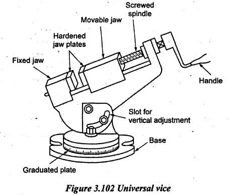
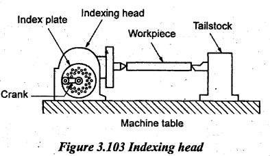
5. WORK HOLDING DEVICES
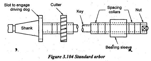
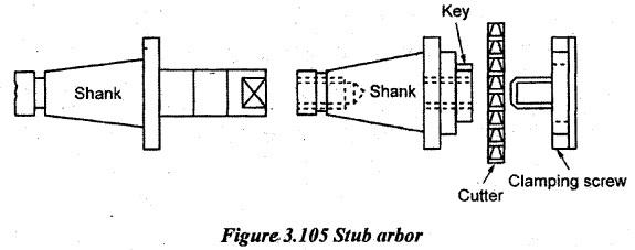
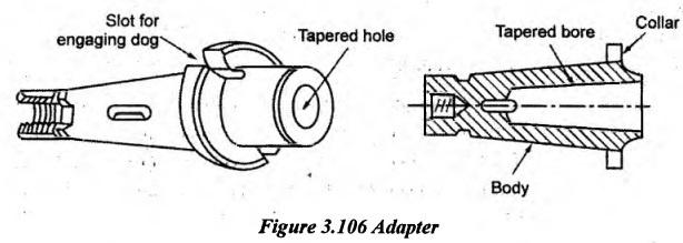
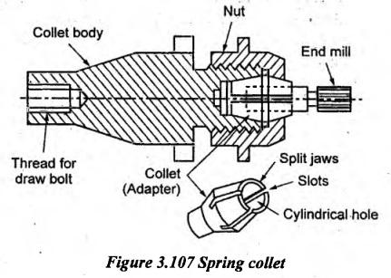
6. TOOL OR CUTTER HOLDING DEVICES
7. MILLING MACHINE ATTACHMENTS
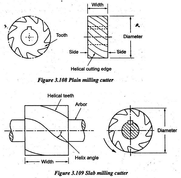
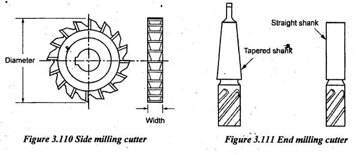
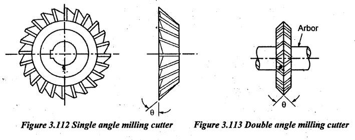
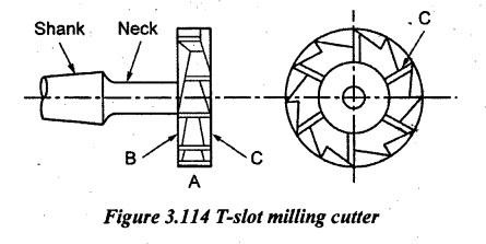
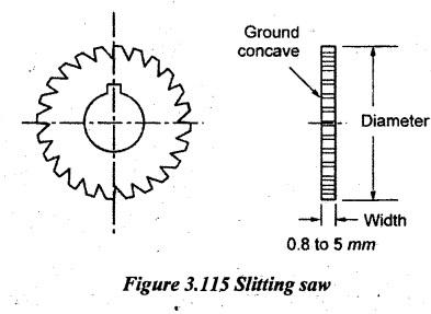
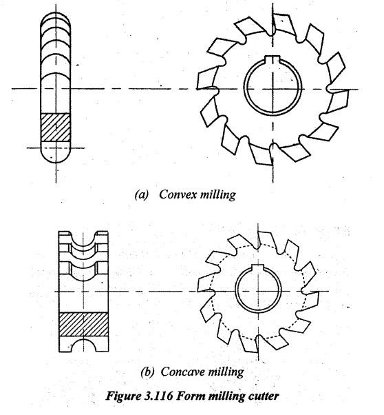
8. TYPES OF MILLING CUTTERS
9. NOMENCLATURE OF MILLING CUTTERS
10. MILLING CUTTER MATERIALS
11. MILLING PROCESSES
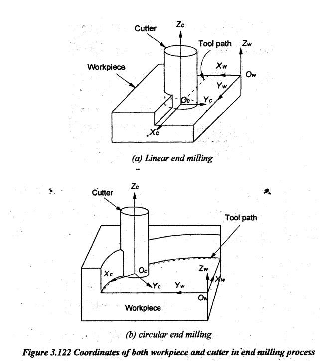
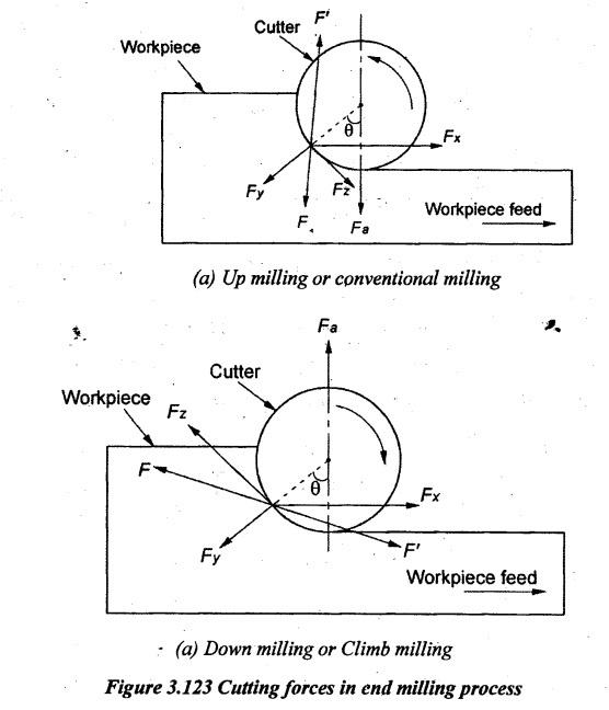
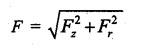
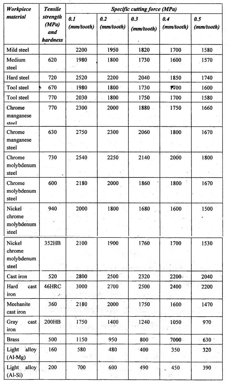
12. CUTTING FORCES IN MILLING PROCESS
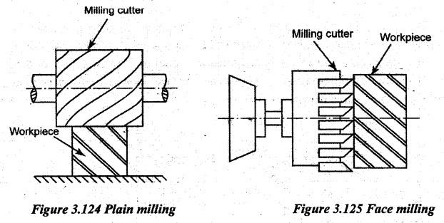
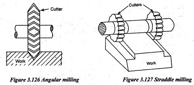
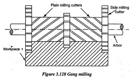
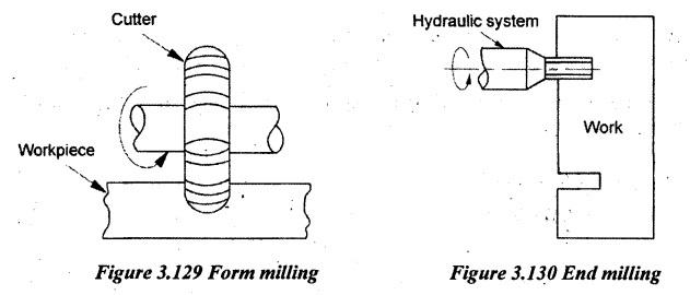
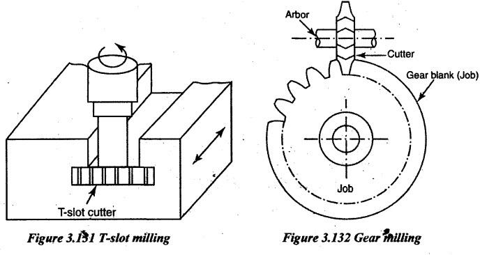
13. MILLING OPERATIONS
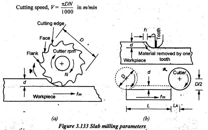
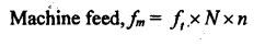
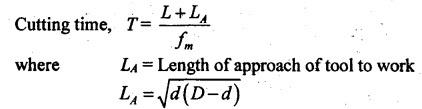
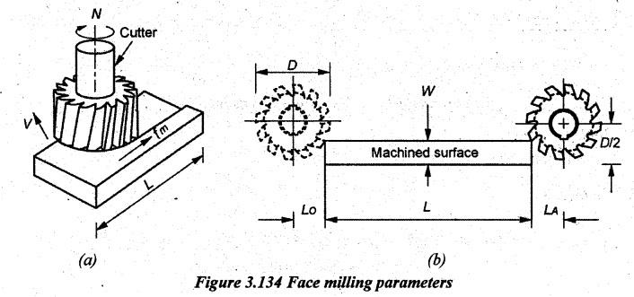
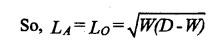
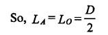
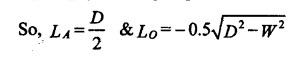
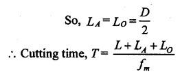
14. CALCULATION OF MACHINING TIME
Manufacturing Technology: Unit III: Reciprocating Machine Tools : Tag: : Reciprocating Machine Tools - Manufacturing Technology - Milling Machine
Related Topics
Related Subjects

Manufacturing Technology
ME3493 4th semester Mechanical Dept | 2021 Regulation | 4th Semester Mechanical Dept 2021 Regulation