Manufacturing Technology: Unit III: Reciprocating Machine Tools
microfinishing or superfinishing
Reciprocating Machine Tools - Manufacturing Technology
It is a finshing process to remove the amorphous surface layer (thermally damaged) caused by grinding.
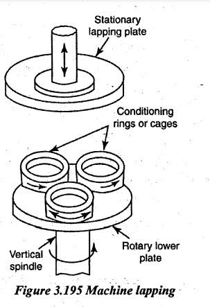
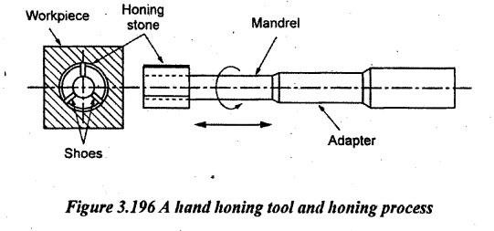
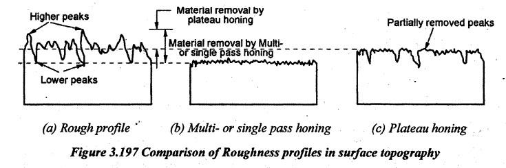
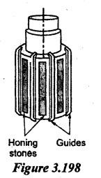
MICROFINISHING OR SUPERFINISHING It is a finshing process to remove the amorphous surface layer (thermally damaged) caused by grinding. Microfinishing is suitable for obtaining a surface of the highest class of finish. It is similar to honing with small allowances but it differs in the large number of different abrasive stones and wheels and also the types of motions. In addition to high surface finish, microfinishing also removes chatter marks, feed spirals, grinding commas and other. imperfections left by the previous grinding operations. In microfinishing, the pressure exerted is very low and stock removal is upto 0.025mm. The contact area of the stone and the workpiece are large. The stone is given oscillating motion while the workpiece is given a rotary motion. Working: Microfinishing can be used to external and internal cylindrical, tapered, flat surfaces. External cylindrical surfaces can be super-finished by oscillating the abrasive stones at amplitude of 1.5mm to 3mm and frequencies of 500 to 1500 cycles per min., reciprocating axially along the rotating workpiece. External cylindrical surfaces can also be super-finished by oscillating and rotating the abrasive stones about the stationary workpiece. Internal cylindrical surfaces can be super finished by axially oscillating and reciprocating abrasive stones applied to the rotating workpiece. Flat surfaces can be machined by rotating cup-shaped abrasive stone with the work resting on a circular rotating table. (Abrasive stone and the circular table are rotating in opposite directions). An additional oscillating movement and hydraulic pressure given are to the abrasive stone for traverse feeding and microfinishing. Cutting speed - 10 to 40 m/min Oscillating Prequencies - 500 to 2000 cycles/min Working pressure - 1 to 4 kg/cm2 Allowance range - 0.002 to 0.02 mm 1. Fluids: Light mineral oil or kerosene mixed with heavier cutting oil is used as coolant to keep the stone clean and sharp. 2. Abrasive stones: This process is suitable to external or internal cylindrical, tapered, flat, curved, spiral surfaces, or where high class of finish is required. Lapping is a surface finishing process used for producing geometrically accurate flat, cylindrical and spherical surfaces. The removal of metal takes place by abrasive action. Lapping is used for (i) Removing small amounts of material from the surfaces of tools. (ii) Removing small defects and surface cracks left during previous operations. (iii) Eliminating small distortion. Lapping consists of the use of loose-grain abrasive flours mixed with oil. Natural as well as artificial abrasives are used for lapping. Aluminium oxide is preferred for lapping soft ferrous and non-ferrous metals. Silicon carbide and natural corundum are used for hardened steel parts. The abrasive carries out the cutting operation. It is sprayed over the workpiece and the lapping operation is carried out by applying light pressure on the lapping tool. The material for lapping tool or lap is softer than the workpiece. Lubricant is used to hold or retain the abrasive grains during the operation. The lubricant is used for this purpose is called 'vehicle'. To some extend, it also controls the cutting action of the abrasive grain. Some common vehicles used in lapping include the vegetable or olive oil, lard oil, water soluble oil, mineral oil, kerosene mixed with a little machine oil and alcohol. 1. Types of Lapping Operations Lapping operations can be broadly classified into the following two main groups. (i) Equalising lapping. (ii) Form lapping. 1. Equalising lapping: It is the operation of running two mating parts or shapes together with an abrasive between them. When two such surfaces run together in constant contact with the abrasive, their surface finish is improved and any deviation of shape is corrected. 2. Form lapping: As name implies, it is not merely rubbing of surfaces together but it is the shape of the lap that is responsible for finishing a corresponding work surface. 2. Cutting Conditions for Lapping 1. Speed: Most efficient lapping speed range - 100 to 250 m/min. Maximum lapping speed for fine lapping of bores - 50 m/min. Maximum cutting speed for lapping flat surface - 250 m/min. 2. Pressure: Pressure ranges for soft materials including non-ferrous metals and loose abrasives are 0.1 to 0.3kg/cm2. Pressure for hard materials -0.7 kg/cm2. Uniform pressure during lapping is to be maintained. 3. Allowances: Allowances for lapping - 0.005 to 0.03 mm. Harder is the material, lower will be the lapping allowance. Tolerance within ± 0.001 mm. 4. Lap materials: For machine lapping - Cast iron. For manual lapping, soft steel, bronze, brass, lead. 5. Lapping abrasive: Silicon carbide-For lapping hardened steel or cast iron. Aluminium oxide - For lapping soft steel and non-ferrous metals. Boron carbide-For lapping dies, gauges etc. Diamond - For lapping tungsten carbide. 3. Lapping Methods and Machirtes Lapping is done in the following two ways. (a) By hand called hand lapping. (b) By machines called machine lapping. 1. Hand lapping: In hand lapping, either the lap or the workpiece is held by hand and the motion of the other enables the rubbing of the two surfaces in contact. This method is widely used in lapping press work dies, moulding dies and metal moulds for casting, limit gauges etc. In some cases, lapping compound is placed between the two surfaces and two are rubbed together by moving one of these by hand, the other remaining stationary. Example: lapping of surface plates, engine valve and valve seat etc. The movement of the workpiece has to be along an irregular path, not just to and fro. Generally, it is moving along a path taking a shape of English numeral '8'. 2. Machine lapping: Machine lapping is performed for obtaining a highly finished surface on many articles like races of ball and roller bearings, gears, crankshafts, machine bearings, pistons, pins and gauges etc. Hand lapping is used in lapping a few components only. For batch production lapping work, lapping machines are used. In machine lapping operation, the two surfaces are rubbed under a load. A fine abrasive suspended in oil is fed in between the surfaces while the operation is in progress. During the operation in progress, the direction of rubbing is changed constantly. Three types of lapping media are used in lapping machines. These are (a) Metal laps and abrasive powders, (b) Bonded abrasive and (c) Abrasive paper or cloth. Metal laps are used on components requiring extreme accuracy. Bonded abrasives are used for commercial production. There are following three types of lapping machines commonly used. (i) Bonded abrasive circular plate lapping machines. These machines are used for lapping flat and circular workpieces. (ii) Bonded abrasive or cast-iron wheel machines. It works on the principle of centreless lapping and is used for lapping circular surfaces. (iii) Internal cylindrical lapping machines. These machines are similar to honing machines. The working principle of typical vertical spindle lapping machine is shown in Figure 3.195. The workpieces are loaded in conditioning rings or cages on the rotary lower plate which rotates about a vertical axis as shown in the same fig. At the same time, the conditioning rings also rotate along with the workpieces in their own positions. The combination of these two rotary motions provides a gyratory motion to the workpieces due to which the entire surface of the two plates is covered. This results in an even wear of the plate surface and therefore, its flatness is maintained. The upper plate just provides a floating action and helps in maintaining parallelism. It is also an abrasive process used for finishing previously machined surfaces. It is mostly used for finishing internal cylindrical surfaces such as drilled or bored holes. The tool used called a hone is a bonded abrasive stone made in the form of a stick. Although honing enables the maximum stock removal out of the entire surface finishing operations, this higher stock removing capacity enables the application of honing for correcting slight out of roundness or taper. The usual amount of stock left for removal by honing is from 0.1-mm to 0.25 mm. Honing is performed at relatively slow speeds in the range of 10-30 metres/min. The honing tool works more or less in the same way as an expanding reamer. The honing stones are so held in a holder or mandrel that they can be forced outwards by mechanical or hydraulic pressure against the surface of the bore. Aluminium oxide, silicon carbide or diamond grains of suitable grit are bonded in resinoid, vitrified or shellac bond to form the honing stones usually carrying impregnated traces of sulphur or wax for longer tool life and better cutting action. Both internal cylindrical and flat surfaces can be honed. But, the process of honing is largely applied to internal cylindrical surfaces only. A hand-honing tool is shown in Figure 3.196. 1. Types of Honing 1. Hand honing process: Honing is a 'wet' process and it is necessary that a suitable coolant being used in ample quantity during the operation. In small parts, honing can be done by hand. In this, the hone is rotated and the workpiece is moved over rotating tool back and forth by hand. The length of stones used is about half of that of the hole and the over travel at the end of each stroke is about one-third of the stone length. 2. Machine honing: The process of honing can be done on many general purpose machines also such as lathes and drilling machines. Where the stationary type of machines do not suit the nature of work, a portable electric drill can be used for this purpose by fitting a hone in place of the drill, the reciprocating motion being given by hand. In production work, where honing is to be done on a large scale, such machines will fail to give satisfactory and economical results. In such cases, the use of regular honing machines only will give the desired results. These honing machines are made in various types and sizes. 2. Methods of Honing Honing methods are divided into three categories as follows: (i) Conventional honing (ii) Single-pass honing (iii) Plateau honing. 1. Conventional honing: In this method, the tool rotates with an abrasive honing stick pressed on a bore surface to perform honing operation. Several strokes of honing are required to complete the honing process to the required surface finish. Also, the work surface is abraded back and forth by the tool. By this honing process, the finished bore to close diameter value with closer tolerances. Accurate size control can be achieved by a suitable automatic size control mechanism. A very high size control of process repeatability can be achieved in this method which ranges from 0.0025 mm to 0.00508 mm. In automatic honing process, only loading and unloading of workpiece and fixture are done manually. Remaining operations are automatically done. This method of honing provides the advantages of closer control (Tolerance) finished diameter size, cylindricity and surface finish. 2. Single-Pass honing In single pass honing, the bore is finished in a single step or single pass of the tool. The honing tool is in the form of a sleeve which is mounted on an expandable tapered arbor. This sleeve and arbor mechanism presses the tool against the work surface to be finished. This process is faster due to single-pass of the tool. Also, the finished surface accuracy is high which is closer to the true to be obtained. During forward stroke of the tool, the material is removed and the tool is withdrawn from the hole during return stoke. This honing method offers the advantages of better size control and process repeatability. The bore finished by this method does not need gauging to inspect the work surface. So, it is used in mass production industries due to reduction in finishing by a single-pass of the tool. 3. Plateau honing It is a two-step process to finish the bore in the workpiece. Rough honing with bigger size abrasive particles is carried out in the first step but in the second step, finish honing is performed for the required to be obtained by using a tool having fine abrasive particles to partially remove only the peaks produced during the first step. So, the second step honing enhances the tribological properties of the work surface and reduces the wear on the work surface which leads to increase the life of the workpiece in practical use. The roughness profiles and micro-structure images of different honing methods are shown in Figure 3.197. 3. Honing Stones Honing stones are abrasive products used to refine the finish of internal bores and external surfaces. Honing stones/sticks are made of hard materials such as aluminium oxide, silicon carbide and diamond. Boning of honing stones may be vitrified clay, resinoid, cork, carbon or metal. The bonding should have optimum strength to hold the grit firmly and it should not slide or rub the surface. The number and distribution of stones depends on the roundness to be corrected. 4. Types of Honing Stones (i) Flexible hones: They have abrasive beads bonded to the ends of bristles. Also, they are used to smooth or refine the finish of internal or external surfaces. (ii) Hand hones or diamond hones: They are designed for the offhand honing of ground cutting-tool edges. (iii) Honing sticks or honing tools: They are used for finishing internal bores. Internal grinding uses smaller-diameter wheels or abrasive products for grinding or finishing the surface of a part's inner diameter. Again honing tools are classified into internal hones and external hones. 5. Specifications of Honing Stones Product specifications for hones and honing tools include width, rotary speed and shank or bore diameter. Hone width is measured in millimeters (mm), centimeters (cm) and meters (m). Also, the rotary speed is expressed in terms of maximum value. The bore is used to mount or hold the abrasive product on a spindle or mandrel. Bore diameter is the inner diameter of the center mount. Shank diameter is the diameter of the integral shank, pin, shaft, or mandrel on mounted points or wheels. Parameters for hones and honing tools also include measurements such as outer diameter. Hones and honing tools are available in various mounting styles. Some products are suitable for hand-held use. Others are with a central hole or bore for mandrel, arbor, spindle or shaft mounting. Hones and honing tools which are usually mounted onto an integral mandrel, pin, arbor or shaft are also available. 6. Features of Honing Stones Abrasive grain type and grit size are important considerations when selecting hones and honing tools. Choices for abrasive grain include the following: (i) aluminum oxide (ii) boron carbide (iii) ceramic (iv) emery or crocus (v) garnet (vi) silicon carbide (vii) cubic boron nitride (CBM) (viii) synthetic diamond (ix) tungsten carbide (x) zirconia. 7. Standards of Honing Stones Grit sizes for hones and honing tools are based on proprietary grading systems or standards such as ANSI, FEPA or JIS. The grading system or standard defines a grit size through specified upper and lower limits at certain points in the size distribution. 8. Types of Honing Machines The most common classification honing machines is as follows: 1. Horizontal honing machines: These machines are mostly used for honing comparatively longer jobs such a gun barrels. All such machines carry a horizontal spindle on which the honing tool is mounted. On some machines, the workpiece is mounted on a table which reciprocates hydraulically to move the work to and fro on the hone which rotates about its own axis and also, simultaneously oscillates a little. The oscillating motion of the hone may be controlled hydraulically or mechanically. In some machines, the work is held in a horizontal position and rotated about its own axis. Reciprocating motion is not given to work. Against this, the honing tool which is mounted on a traveling head is rotated and reciprocated to perform the honing process. The latter type of machine is used for extremely long jobs. A suitable gauge is always provided to check the correct size. These machines may carry a single or double spindle. 2. Vertical honing machines: These machines hold the work as well as the tool in vertical positions. They are available in both single and multiple spindle types. Usually, the spindle heads with the tools reciprocate but the workpieces are not reciprocated. Suitable fixtures are usually employed to hold the workpieces in position. Most of the modern machines carry a hydraulic drive for their spindle heads and the tools. These machines are best suited for shorter jobs. In appearance, these machines resemble the drilling machines. In honing work, the vertical machines are widely used than the horizontal ones. A honing tool head used on vertical honing machines is shown in Figure 3.198. 9. Honing Conditions All materials can be honed but the material removal rate is based on the hardness of the work material. For examples, (i) Soft material can be honed up to 1.15 mm/min on diameter and hard material can be honed up to 0.3 mm/min on diameter. (ii) The maximum bore size can be honed about 1500 mm and the minimum size can be honed up to 1.5 mm in diameter. (iii) According economic point of view, the honing allowance should be minimum which is mainly based on the amount of error to be correcting. (iv) The selection of abrasive and grain size mainly depends on the work material and true value decided. 10. Cutting Fluids for Honing Process A proper fluid is used to reduce heat generation in honing process. Its main functions are to clean the small chips from stones and workpiece, to cool work and hone, and to lubricate the cutting action. A fine mesh filtering system must be used since recirculated metal can spoil the finish. Honing oil can improve stock removal rates by helping the cutting action of the abrasive grains. It prevents pickup (spot welding of tool to bore) and loading (chips coating the stone). Honing oil does not acting as a coolant but it does above-mentioned functions through chemical activity. Honing oil is a liquid, solution or emulsion used to aid in the cutting or grinding of metal by abrasive tools or stones and may or may not contain oil. It is also called machining oil, tool oil, cutting fluid and cutting oil. The two most common classes of honing oil are petroleum based which are mineral oils and non-petroleum which are water based oil or vegetable based oil. Common additives include chlorine, sulfur, rust inhibitors and detergents. Honing oil has just the right consistency for sharpening stones. It will not gum it up nor glaze it and it will provide just enough lubrication to avoid wearing out the stone prematurely. Honing oil: Honing is primarily used with a provision for flushing but not for cooling. The viscosity of oil should be low to enhance Material Removal Rate (MRR) and productivity of the process. The honing grooves, volume and direction of the valleys control the amount of oil retained and its uniform spread on the bore surface. 11. Difference between Honing and Micro Finishing 1. It is possible to create dimensions. i.e., the desired size through honing while microfinishing is employed only for obtaining a high quality surface finish with no appreciable amount of stock removal. 2. The honing process needs only two motions whereas microfinishing may involve many. With the result, the path of an abrasive grain is never repeated. 3. The honing process is mostly employed for finishing internal surfaces, whereas microfinishing is largely used for outside surfaces. 4. Microfinishing is done at much lower operating speeds than honing. 5. The total pressure on the work is too low in microfinishing as compared to honing enabling finishing of even the very delicate parts. 6. The length of stroke in microfinishing is very short usually 1.5 mm to 6 mm as compared to honing. With the result, there is no appreciable accumulation of chips and therefore, no scratches are produced on the job surface. Applications of honing process: The honing processes are used in the following components such as 1. Diesel engine cylinder bore 2. Roller bearing races 3. Bores of cannons 4. Automobile, aeroplane engine cylinder head bores 5. Bores in rocker arms 6. Hub holes in gears of gear boxes. Advantages of honing process: 1. Correction of geometrical accuracy such as out of roundness, taper and axial distortions. 2. Dimensional accuracy 3. High productivity as compared to lapping 4. Holes of any diameter or length may be honed. 5. Several holes may be simultaneously honed on multiple spindle machines. Disadvantage of honing process: Non-ferrous metals are difficult to hone due to glazing and clogging of the voids of the abrasive sticks. 12. Surface Roughness Obtainable in Lapping and Honing Operations As the name of this group of abrasive operations suggests, their objective is to achieve superior surface finish up to mirror-like finishing and very close dimensional precision. The finishing operations are assigned as the last operations in the single part production cycle usually after the conventional or abrasive machining operations, but also after net shape processes such as powder metallurgy, cold flash less forging, etc. The following Table 3.7 shows typical maximum and minimum roughness average (Ra) values that can be produced on various finishing processes. Table 3.7 Surface roughness obtainable in finishing operations
1. CUTTING CONDITIONS FOR MICROFINISHING
2. LAPPING
3. HONING

Manufacturing Technology: Unit III: Reciprocating Machine Tools : Tag: : Reciprocating Machine Tools - Manufacturing Technology - microfinishing or superfinishing
Related Topics
Related Subjects

Manufacturing Technology
ME3493 4th semester Mechanical Dept | 2021 Regulation | 4th Semester Mechanical Dept 2021 Regulation