Engineering Graphics: Unit II (c): Projections of Straight Lines
Method of Drawing Traces on Projections of lines
Engineering Graphics (EG)
When the line is parallel to both the planes then the projections are parallel to XY, since the line does not meet both HP and VP, it has no H.T and V.T.
METHOD OF DRAWING TRACES ON PROJECTIONS OF LINES Case (i): Line is parallel to both HP & VP Refer Fig. 12.49. When the line is parallel to both the planes then the projections are parallel to XY, since the line does not meet both HP and VP, it has no H.T and V.T. Case (ii): Line is parallel to HP and perpendicular to VP. Refer the Fig. 12.50. Draw the top view and the front view. Since the line is parallel to HP, top view is a straight line having true length and since the line is perpendicular to VP, front view is a point. When the line is produced its V.T coincide with its front view and has no H.T. Hence draw the projections of V.T, v' coinciding with its front view and v on the vertical projector drawn through v' and lies on the reference axis XY. Case (iii): Line is parallel to VP and perpendicular to HP Refer the Fig. 12.51. Since the line is parallel to VP, its front view is a straight line having true length and since the line is perpendicular to HP, its top view is a point. Draw the front view and top view. When the line is produced it will meet HP at H.T and has no V.T. Hence draw the projections of H.T, h coinciding with its top view and h' lies on XY on the projector drawn through h. Case (iv) : Line is parallel to HP and inclined to VP Refer Fig. 12.52. The line is parallel to HP and inclined to VP. Hence top view is a straight line having true length and true inclination and the front view is a straight line having shorter length and parallel to XY. Draw the top view and front view. Since the line is parallel to HP it has no H.T and since the line is inclined to VP, it will meet VP at V.T, if produced. To draw the projections of V.T, extend the top view to meet XY at v. Through the point v draw a vertical projector to cut the horizontal line, produced from front view at v'. v' and v are the projections of V.T. Case (v): Line is parallel to VP and inclined to HP Refer the Fig. 12.53. The line is parallel to VP and inclined to HP. Hence front view is a straight line having true length and true inclination and the top view is a straight line having shorter length and parallel to XY. Draw the front view and top view. Since the line is parallel to VP it has no V.T and since the line is inclined to HP, it will meet HP at H.T, if produced. To draw the projections of H.T, extend the front view to meet XY at h'. Through the point h' draw a vertical projector to cut the horizontal line, produced from top view at h. Now h' and h are the projections of H.T. Case (vi): Line is inclined to both HP and VP Refer the Fig. 12.54. When the line is inclined to both the planes both front view and top view are straight lines having shorter length than the true length and greater inclinations with HP and VP than the true inclinations. Also when the line is produced it will meet both HP and VP since it is inclined to both the planes. Hence it has both H.T and V.T. Draw the front view and top view of the given line by following a suitable method according to the given data as explained from examples 11 to 22. To draw the projections of H.T Extend the front view to meet XY at h'. Draw a vertical projector through h' to meet the top view produced at h. h' and h are the projections of H.T. To draw the projections of V.T Extend the top view to meet XY at v. Draw a vertical projector through v to meet the front view produced at v'. v and v' are the projections of V.T. Example 23: A line AB is inclined at 35° to VP and has its ends A and B 25 mm and 55 mm above HP respectively. The length of the front view is 60mm and its vertical trace (V.T) is 15mm above HP. Draw the projections of straightline. Also determine the true length and true inclinations of straight line. 1. Draw the reference line XY and mark a point O. 2. Mark the front view of the end a' 25mm above XY on the projector through O. 3. Draw the locus line of end b' 55mm above XY and parallel. 4. With a' as centre and 60mm as radius (ie., length of front view) draw an arc to cut the locus line of b' at b'. Join a' and b' which is the required front view of the line AB. 5. Draw the locus line of V.T, 15mm above (given in the problem) XY and parallel. Extend the front view a'b' to cut the locus line of V.T at V.T and mark the top view of V.T on XY as v. 6. Through v draw a line at 35° to XY (given in the problem, inclination of line with VP is 35°) to cut the vertical projector drawn through a' at a and extend. 7. With a' as centre and a'b' as radius draw an arc to cut the horizontal line drawn through a' at b2, And then draw a vertical projector through b2' to cut the inclined line drawn through a at b2. 8. Draw the locus line of b, parallel to XY and passing through b2. 9. Draw a vertical projector through b' to cut the locus line of b at b. Join a and b which is the required top view. 10. Taking a as centre and ab as radius draw an arc to cut the horizontal line drawn through a at b1 and from b1 draw a vertical projector to cut the locus line of b' at b1'. Join a' and b1' which gives the true length of line. 11. Extend ab to cut the vertical projector drawn through h' at H.T. 12. Measure the true inclinations of line with HP and VP ie., angle made by a'b1', with XY (θ). Also measure the true length of the line 'l' (ie., a'b1' or ab2) (Ans: l = 72 mm; θ = 24°).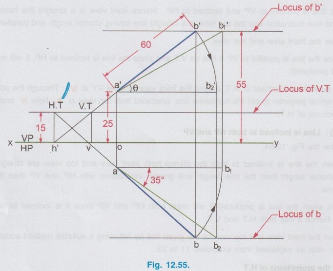
Engineering Graphics: Unit II (c): Projections of Straight Lines : Tag: : Engineering Graphics (EG) - Method of Drawing Traces on Projections of lines
Related Topics
Related Subjects

Engineering Graphics
GE3251 eg 2nd semester | 2021 Regulation | 2nd Semester Common to all Dept 2021 Regulation