Hydraulics and Pneumatics: Unit II: Hydraulic Actuators and Control Components
mechanical-type servo valve (or hydromechanical servo valve)
Hydraulic Actuators and Control Components - Hydraulics and Pneumatics
This type of servo valves is generally used for positioning control.
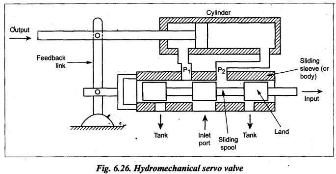
MECHANICAL-TYPE SERVO VALVE (OR HYDROMECHANICAL SERVO VALVE) This type of servo valves is generally used for positioning control. The construction and operation of a typical mechanical-type servo valve is illustrated in Fig.6.26. The shape of the porting in the sleeve may be square, rectangular, round, or full annulus. First a small input force is applied to the spool. This shifts the spool towards right to a position which allows the oil to enter through port P1 from inlet port. Now the oil flows into the hydraulic cylinder and thus the cylinder retracts towards right. Since the feedback link is connected with the piston rod and the sliding sleeve as shown in Fig.6.26, the feedback link shifts the sliding sleeve towards right until it blocks off the flow to the hydraulic cylinder through P1. Thus the given input motion has produced a specific and controlled amount of output motion and also the output motion is fedback to modify the input via the feedback line. As for the axial alignment between the lands on the spool and the porting in the sleeve or body, different 'lap' conditions are employed. Lap is the length relationship between the metering lands of the spool and the port openings in the sleeve or body. (i) Closed centre servo valve : It has an overlapped condition. In this, the lands are slightly longer than the porting area and create a dead zone. But a dead zone is not desirable in a servo valve as it makes the valve unresponsive to small signals. (ii) Open centre servo valve : It has an underlap condition in that the lands on the spool are somewhat narrower than the port holes in the sleeve. In the center position of the spool, there is a constant fluid flow from the pressure inlet, across the spool to the tank port. Pressure drop due to such restrictions causes an intermediate pressure at the cylinder ports. (iii) Zero lap servo valve: It is the most desirable construction. This 'zero lap' means, that the edges of the spool lands are precisely made to line up with the metering ports in the valve sleeve. The reason for the accurate axial fit is to eliminate a dead zone. Thus any movement of the spool in either direction from its centered position will cause a corresponding flow. The position of the spool in the sleeve controls both flow rate and direction of flow. Mechanical-type servo valves are generally employed in the less complex systems. Application for hydromechanical servo valves are on steering devices (such as power steering system of automobiles); test and training devices; copying devices (such as on machine tools); and heavy-duty mobile equipment.1. Construction
2. Operation
3. Different 'Lap' Conditions
4. Application of Hydromechanical Servo Valve
Hydraulics and Pneumatics: Unit II: Hydraulic Actuators and Control Components : Tag: : Hydraulic Actuators and Control Components - Hydraulics and Pneumatics - mechanical-type servo valve (or hydromechanical servo valve)
Related Topics
Related Subjects

Hydraulics and Pneumatics
ME3492 4th semester Mechanical Dept | 2021 Regulation | 4th Semester Mechanical Dept 2021 Regulation