Basic Electrical and Electronics Engineering: Unit V: Measurements and Instrumentation
Measurement of Power in Three Phase Circuits
Three wattmeter method : The connections as employed for a 3 phase 4 wire system are shown in fig. 5.11
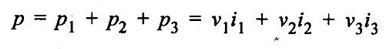
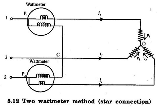
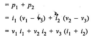
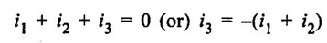
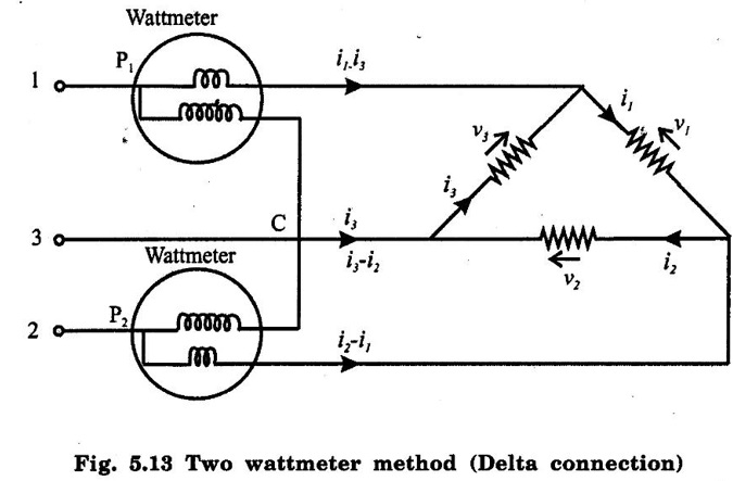
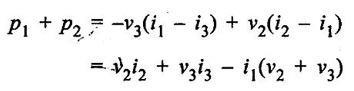
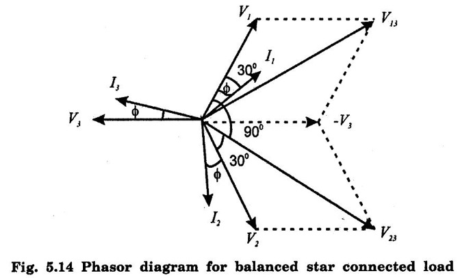
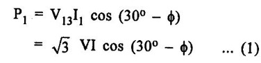
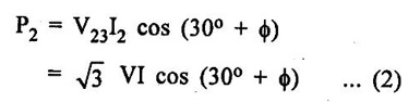
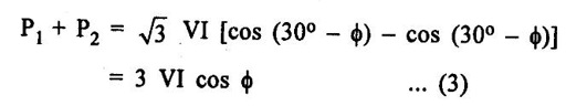
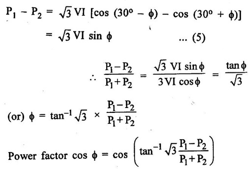
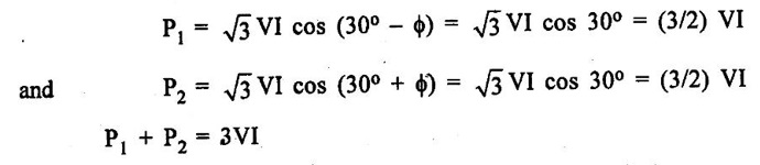
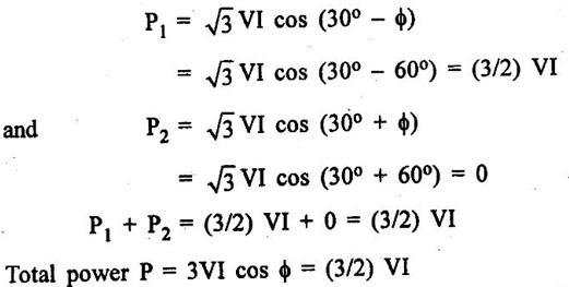
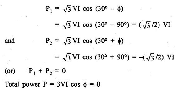
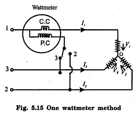
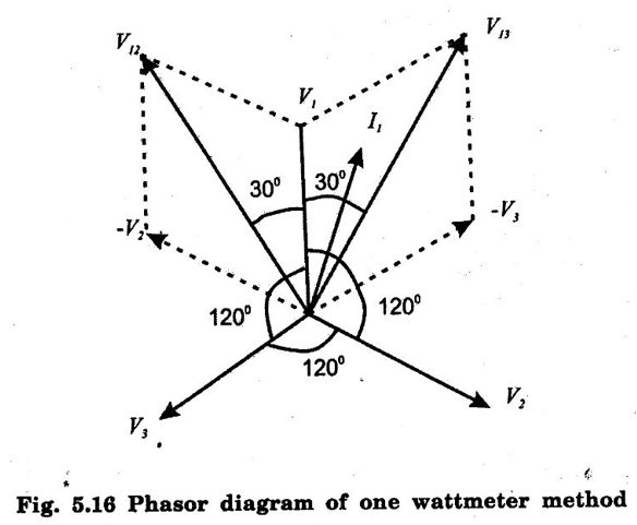
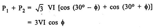
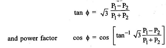
MEASUREMENT OF POWER IN THREE PHASE CIRCUITS 1. Three wattmeter method : The connections as employed for a 3 phase 4 wire system are shown in fig. 5.11 In this case, the common point C of pressure coils and the neutral O of the load concide and therefore, ν = 0 and ν1 = ν1', v2 = ν2', v3 = ν3' Sum of the instantaneous reading of the wattmeters. Instantaneous power of load Hence these three wattmeters measure the power of the load. 2. Two wattmeter method: In a three phase three wire system we require 3 elements, but if we make the common points of the pressure coils coincide with one of the lines, then we will require only n – 1 = 2 elements. Instantaneous power consumed by load Let us consider two wattmeters connected to measure power in three phase circuit as shown in fig. 5.12 (Star connection) and fig. 5.13 (Delta connection) Star (Wye) Connection: Instantaneous reading of p1 wattmeter p1 = i1 (v1 - v3) Instantaneous reading of p2 wattmeter p2 = i2 (v2 - v3) Sum of instantaneous readings of two wattmeters From Kirchhoff's law (Fig. 5.12) ⸫ Sum of instantaneous readings of two wattmeters = v1 i1 + v2 i2 + v3 i3 Therefore, the sum of the two wattmeter reading is equal to the power consumed by the load. This is irrespective of whether the load is balanced or unbalanced. Delta Connection: Instantaneous reading of p1 wattmeter. p1 = - v3 (i1 - i3) Instantaneous reading of p2 wattmeter p2 = v2 (i2 - i1) ⸫ Sum of instantaneous readings of wattmeters p1 and p2; From Kirchhoff's voltage law, Hence sum of instantaneous readings of two wattmeters Therefore, the sum of the two wattmeter readings is equal to the power consumed by the load. This is irrespective of whether the load is balanced or unbalanced. Fig. 5.14 shows the phasor diagram for a balanced star connected load of fig. 5.12 Let V1, V2, V3 be the rms values of phase voltage and I1, I2, I3 be the rms values of phase currents. The load is balanced, therefore, Phase voltages, V1 = V2 = V3 = V (say) Line voltages, V13 = V23 = V12 = √3V Phase currents, I1 = I2 = I3 = I (say) Line currents, I1 = I2 = I3 = I Power factor = cos ϕ. The phase currents lag the corresponding phasor voltages by an angle ϕ. The current through wattmeter P1 is I1 and voltage across its pressure coil is V13. I1 leads V13 by an angle (30° – ϕ). ⸫ Reading of P1 wattmeter, The current through wattmeter P2 is I2 and voltage across its pressure coil is V23 I2 lags V23 by an angle (30° + ϕ) ⸫ Reading of P2 wattmeter, Sum of reading of two wattmeters : This is the total power consumed by load. ⸫ Total power consumed by load P = P1 + P2 ……. (4) Difference of readings of two wattmeters Effect of power factor on the readings of wattmeters : (a) With unity p.f. cos ϕ = 1 and ϕ = 0 The readings of the two wattmeters are : At unity power factor, total power = P = 3VI cos ϕ = 3VI Thus at unity power factor, the readings of the two wattmeters are equal, each wattmeter reads half of the total power. (b) When p.f = 0.5, we have ϕ = 60° Therefore, Therefore, when the power factor is 0.5, one of the wattmeters reads zero and the other reads total power. (c) When p.f = 0, we have ϕ = 90°. Therefore, Therefore, with zero power factor, the readings of the two wattmeters are equal but of opposite sign. It should be noted that when the power factor is below 0.5, one of the wattmeters will give negative indication. Under these conditions in order to read the wattmeter, we must either reverse the current coil or the pressure coil connections. The wattmeter will then give a positive reading but this must be taken as negative for calculating the total power. 3. One wattmeter method : The method can be used only when the load is balanced. The connections are shown in fig. 5.15. The current coil is connected in one of the lines and one end of the pressure coil to the same line, other end being connected altemately to the other two lines. The phasor diagram is shown in fig. 5.16. We have, V1 = V2 = V3 = V I1 = I2 = I3 = I and V13 = V12 = √3V Reading of wattmeter when the switch is at 3: Reading of wattmeter when the switch is at 2: Sum of the two wattmeter readings, Thus the sum of the two readings is the power consumed by the load, or P = P1 + P2 Proceeding as in the case of two wattmeter method,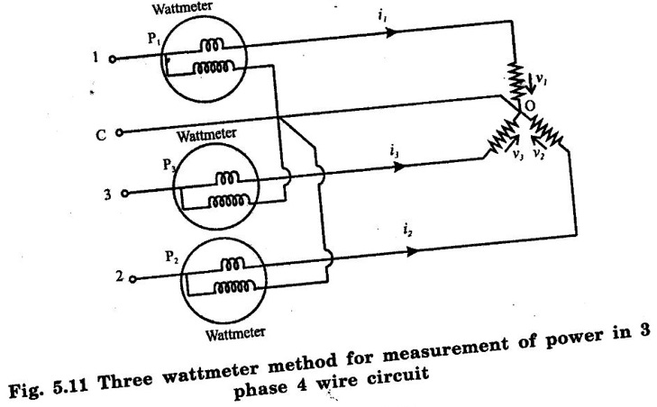


Basic Electrical and Electronics Engineering: Unit V: Measurements and Instrumentation : Tag: : - Measurement of Power in Three Phase Circuits
Related Topics
Related Subjects

Basic Electrical and Electronics Engineering
BE3251 2nd semester Mechanical Dept | 2021 Regulation | 2nd Semester Mechanical Dept 2021 Regulation

Basic Electrical and Electronics Engineering
BE3251 2nd Semester CSE Dept 2021 | Regulation | 2nd Semester CSE Dept 2021 Regulation