Manufacturing Technology: Unit IV: CNC Machines
machining centers
CNC Machines - Manufacturing Technology
A machining center is a highly automated machine tool capable of performing multiple machining operations under computer numerical control in one setup and it can work on more than one face of a component with minimal human attention.
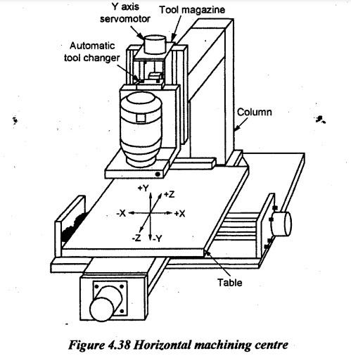
MACHINING CENTERS A machining center is a highly automated machine tool capable of performing multiple machining operations under computer numerical control in one setup and it can work on more than one face of a component with minimal human attention. A CNC machining center accomplishes a rotating spindle operation but a CNC turning center performs a turning type operation. Workers are needed to load and unload component which usually takes considerably less time than the machine cycle time, so one worker may be able to tend more than one machine. Machining centers are among the most popular types of CNC machines these days. The following operations can be carried out on a machining center. 1. Milling 2. Drilling 3. Reaming 4. Boring 5. Tapping. CNC machining centers are usually designed with features to reduce non-productive time. These features are as follows: (i) Automatic tool changer: The tools are contained in a storage unit that is integrated with the machine tool. When a cutter needs to be changed, the tool drum rotates to the proper position and an automatic tool changer (ATC) operating under program control exchanges the tool in the spindle from the tool storage unit. (ii) Automatic component positioner: Many horizontal and vertical machining centres have the capability to orient the component relative to the spindle. It is accomplished by means of a rotary table on which the component is fixtured. The table can be oriented at any angle about a vertical axis to permit the cutting tool to access almost the entire surface of the component in a single setup. (iii) Automatic pallet changer: Machining centres are often equipped with two or more separate pallets that can be presented to the cutting tool using an automatic pallet changer. There are machining centres with six, eight or more pallets. Workpieces can be set up in all pallets and the machine can be programmed to accept a new pallet when work on the previous pallet is completed. While machining is carried out with one pallet in position at the machine, the other pallet is in a safe location away from the spindle. In this location, the operator can unload the finished part and then fixture the raw work part for next cycle. (iv) Multiple operations in one setup: Most components require more than one operation to completely machine the specified geometry. Components having complex geometry may require many distinct machining operations, each requiring its own machine tool, setup, and cutting tool. Machining centres are capable of performing most or all of the operations at one location. Thus, it minimizes the setup time and production lead time. According to the spindle configuration, machining centres are classified as follows: 1. Horizontal spindle machining centre 2. Vertical spindle machining centre 3. Universal machining centre. 1. Horizontal spindle machining centre A horizontal spindle machining centre has the spindle oriented in the horizontal position. These are generally single spindle machines with automatic tool changers. They are generally bed type machines. A typical horizontal spindle machining centre configuration is shown in Figure 4.38. The table of most horizontal machining centres can rotate by either an indexer or a rotary axis. This feature helps in multiphase machining at different angles in a single setup. Many horizontal machining centres manufactured today will also have an automatic pallet changer. It allows the operator to be loading one workpiece while the machine is running another. Since the horizontal machining centre allows access to any side of the workpiece, more machining operations can be done per setup. The axes of horizontal spindle machining centre are given below. X axis ⇒ Table or column motion left to right as viewed from the spindle Y axis⇒ Spindle head motion up and down Z axis⇒ Saddle / column / spindle head motion toward and away from the spindle. 2. Vertical spindle machining centre A vertical spindle machining centre has the spindle oriented in the vertical position. These are also bed type machine. It also contains an automatic tool changer to allow tools to be loaded into the spindle without operator intervention. A typical vertical spindle machining centre configuration is shown in Figure 4.39. Basic vertical machining centres will allow three directions or axes of motion as follows. X axis ⇒ Table or column motion left to right as viewed from the spindle Y axis ⇒ Saddle or table motion toward and away from the spindle Z axis ⇒ Spindle head or headstock motion up and down. Some vertical spindle machining centres have the table that can rotate by either an indexer or a rotary axis. This feature allows more than one surface of the workpiece to be machined during a machining cycle. The axis of rotary table is parallel to Z-axis and it is called 'B' axis. The biggest limitation of a vertical machining centre is that the spindle can only access one side of the workpiece at a time unless the machine is attached with the rotary device. It makes programming for the typical vertical machining centres easier than the horizontal machining centres. 3. Universal machining centre Universal machining centres are similar to horizontal machining centres but it is with the spindle axis capable of tilting from horizontal to the vertical position. This feature allows ease of machining inclined surfaces. In some machines, the table can be tilted instead of the spindle. In these machines, all the five sides of a component can be machined in a single setup as it is possible to access the top surface of the workpiece mounted on a horizontal machining centre. The other features of the universal machining centre are listed below. (i) It has a single spindle. (ii) It has five axes of machine. (iii) The flexibility is more than other two types. (iv) Tool breakage detection is possible. (v) Automatic loading and unloading of the workpiece are possible. Advantages of universal machining center: (i) It eliminates handling and waiting time between machines (ii) It reduces number of fixtures and setups (iii) It reduces programming time (iv) It improves product quality (v) It ensures less work-in-process (WIP) inventory (vi) It provides faster product delivery to customers (vii) It lowers manufacturing costs. Need of work hold methods in CNC machining process: When machining anything, the stiffness of the entire operation is very important. The reduction in stiffness will cause vibration and hence significant decrease in the accuracy and precision of machining process. Even a slight movement during machining results in poor accuracy. If multiple parts are machined with a poor setup, each part will be significantly different from the rest by resulting in low precision. Manufacturing effort should also be considered to analyse about work holding setup. With work holding solution, the number of machining setups can be reduced. By designing useful features for fixturing into the part, the effort and cost of machining can be reduced. Uses of work holding devices: (i) To ensure proper part immobilization (ii) To minimise part deformation (iii) To use short part clamping (iv) To reduce unclamping time (v) To access the machining area (vi) To increase the ability to absorb machining efforts. Work holding devices: There are a range of workholding methods and devices used on CNC lathes as follows: (i) Vice: A vice can function as a manually mounted piece of equipment, or it can be a machine operating device. A vice can be clamped down to the table of CNC machine. A vice for parts' can be used with parallel edges. The vice make should be levelled to more accurate parts in repeatable numbers. A good work holding method for any part that needs to be held securely but has an irregular form factor are soft jaws. Soft jaws are a set of two parts machined out of aluminum. Each part is flat and straight on one side and has the profile for the part to be machined into the other side. Each soft jaw is bolted to a side of the vise once it's ready to be used. Soft jaws are useful because aluminum is quick and easy to machine. Soft jaws can be reused if you are machining multiple units of the same design. Refer Chapter 2.19.8 on page 2.74. (iii) Collets: Refer Chapter 2.19.8 on page 2.74. (iv) Face plates: Refer Chapter 2.8.3 on page 2.21. (v) Step clamps: Step clamps are also known as toe clamps. It is the most common workholding method for manual milling. This clamping system utilizes the T-slots on a machine's bed because they are an extremely firm way of holding down the workpiece and effective CNC workholding method. (vi) Fixture plates: Fixture plates are used to mount a wide range of parts to be CNC machined. They are made of aluminum or steel and have a grid of holes. Some of these holes are intended for dowel pins and some are threaded for bolts. Fixture plates are useful workholding method due to their repeatability. The dowel pin holes are useful for locating the fixture or part on the plate. The threaded holes are good for bolting down the fixture or part. There are a couple many methods to use a fixture plate. 1. In first method, it is to design in bolting holes to the part. It allows to have access to multiple sides of the part and machine interesting geometries or surfaces. Also, it will require post-processing to remove the fixture holes. 2. In second method, it is to design a custom fixture that holds the part. It provides the advantage of the locating features of the fixture plate. Fixture plates also protect the table of CNC machine from a wayward tool. There are many options for nuts, bolts and other tools to use with a fixture plate. Advanced applications of fixture in CNC machining: With creative fixturing, a lot of different geometries can be machined. Some special kind of fixture are designed and manufactured to machine more complex on a 4- or 5-axis machine. Similarly, it is done for 5th axis machines. With the additional range of motion, the machine has much greater access to the workpiece. Some clearance should be left around the workpiece and machine table for the cutting tools to move. (vii) Pallet changers: Many CNC machining centres provide the capability to load and unload workpieces off-line. It is achieved using pallet changers which are an integral part of the machine tool. The workpiece is clamped to the pallet in a pre-determined position and is loaded into the machine tool to be machined. The empty pallet is loaded with the next workpiece while machining the first workpiece. The pallets are interchanged and the machined workpiece are removed and workpiece loaded ready for machining while the second workpiece is machined. The main methods of interchanging two pallets are linear or rotary.1. Classification of Machining Centre

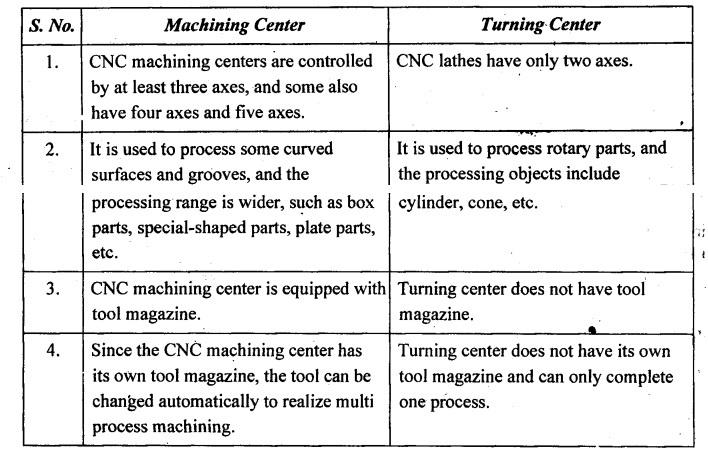
2. Comparison between Machining Center and Turning Center
3. Work Holding Methods in Turning and Machining Centres
(ii) Chucks:
Manufacturing Technology: Unit IV: CNC Machines : Tag: : CNC Machines - Manufacturing Technology - machining centers
Related Topics
Related Subjects

Manufacturing Technology
ME3493 4th semester Mechanical Dept | 2021 Regulation | 4th Semester Mechanical Dept 2021 Regulation