Manufacturing Technology: Unit II: Turning Machines
lathe operations
Turning Machines - Manufacturing Technology
In order to complete a job, several operations are required. The various operations carried out on a lathe are:
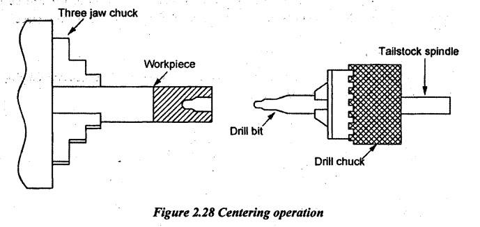
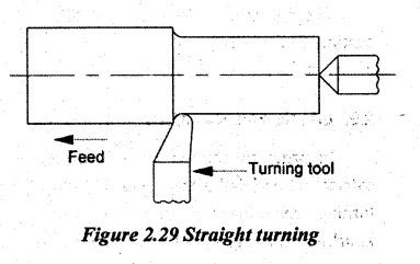
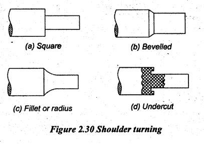
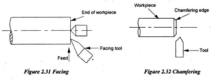
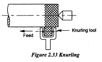
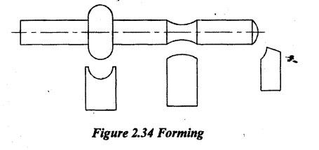
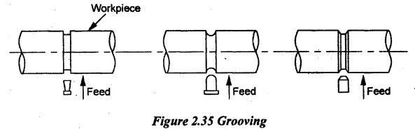
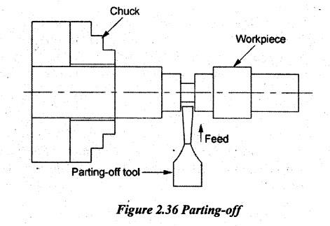
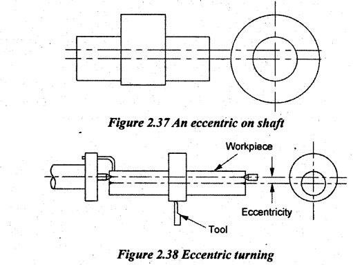
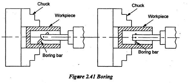
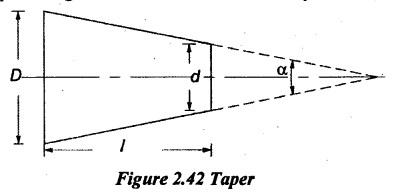
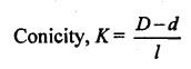
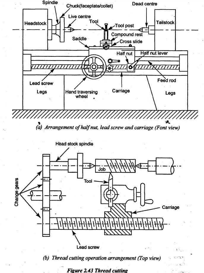
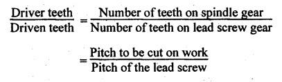
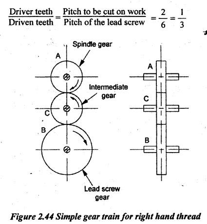
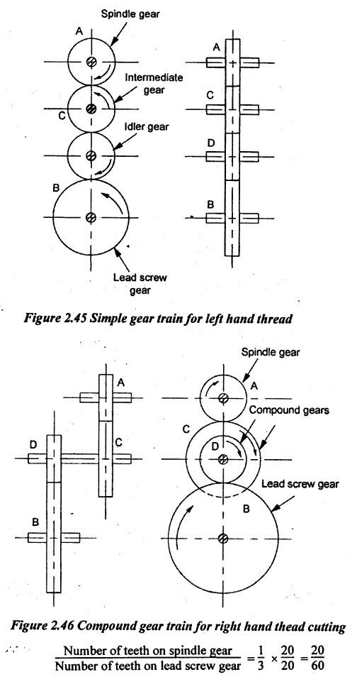
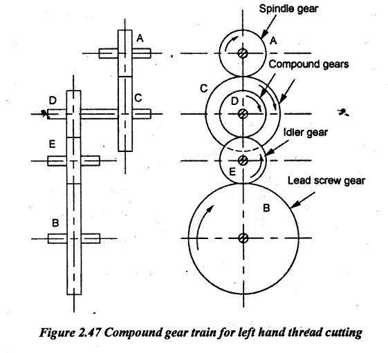
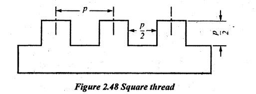
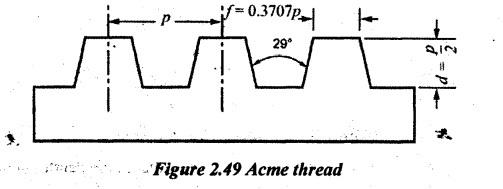
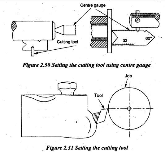
LATHE OPERATIONS In order to complete a job, several operations are required. The various operations carried out on a lathe are: centering, straight turning, taper turning, eccentric turning, shoulder turning, chamfering, thread-cutting, facing, parting-off, drilling, boring, reaming, tapping, knurling, filing, grooving, spinning, forming, milling, grinding etc. When the work is required to be turned between centres, conical shape holes must be provided at both ends of the workpiece to provide the bearing surface for lathe centres. Centering is the operation of producing conical holes on both ends of the workpiece. 'First, the centres of the workpiece ends are marked by using a centre punch. The workpiece is held by a three-jaw chuck. The drill bit is held using a tailstock with a drill chuck or socket. When the job rotates, the drill bit moves into the work by turning the tailstock hand wheel and makes conical shaped holes. Straight turning is the operation of producing a cylindrical surface by removing material from the outside diameter of a workpiece. It is done by rotating the workpiece about the lathe axis and feeding the tool parallel to the lathe axis. The job is held between centres or held in the chuck. The trueness or centreness of the workpiece is checked by a dial indicator or a scriber against the rotating workpiece. A right-hand turning tool is clamped on the tool post. For light cuts, the tool may be inclined towards the headstock but the tool may be inclined towards the tailstock for heavy cuts. The automatic or hand feed can be used. There are two types of straight turning: (a) Rough turning (b) Finish turning. 1. Rough turning: For rough turning, the rate of feed of the tool is fast and depth of cut is heavy. The depth of cut for this turning is about 2 mm to 5 mm and the feed rate is about 0.3 to 1.5 mm per revolution. For rough turning, the rough turning tool is used. 2. Finish turking: For finish turning, the high cutting speed, the light feed and the depth of cut are required. A finish turning tool having a sharp cutting edge is used. The depth of cut will be from 0.5mm to 1 mm and the feed rate is from 0.1 to 0.3 mm per revolution of the workpiece. The stepped diameter workpieces are turned at the shoulder. It is called shouldering. The various types of shoulders are shown in Figure 2.30. For turning square shoulder or bevelled shoulder, a right hand facing tool is used. A round nose tool is used to produce radius shoulder. For making undercut shoulder, a parting- off tool may be used. Machining the end of the workpiece to produce flat surface is called fäcing. The work may be held in a chuck or between centres. The work is rotated about the lathe axis. A facing tool is fed perpendicular to the axis of the lathe. The feeding may be done by hand or power. Chamfering is the process of bevelling or turning a slope at the end of the workpiece. It is done for removing burrs and blends the sharp edges. Generally, the chamfering is done for jobs after knurling, rough turning and thread cutting operations. A chamfering tool is moved perpendicular to the lathe axis. Knurling is the process of producing a diamond shaped pattern or impression on the surface of the workpiece. It is used to give a good gripping surface to the workpiece. It is also slightly done to increase the diameter of the workpiece. A knurling tool is used to produce knurled surfaces. A knurling tool has two hardened steel rollers. The rollers have teeth out on their cylindrical surface. The teeth may be fine, coarse or medium. The tool is held in the tool post and pressed against the rotating work as shown in Figure 2.33. The automatic speed may be given to the tool. Very slow speed and light feed are used. A knurling tool will not cut the metal, instead produce the impression on the workpiece. After the first cut is over, the tool should not be drawn back. It should be reversed in the direction to bring the tool into the starting position before giving the next cut. Filing is the process of removing burrs, sharp corners and feed marks on a workpiece by removing very less amount of metal. It is also used to bring the workpiece into the required size during finishing operation. The operation consists of passing a flat single cut file over the rotating workpiece. A very high cutting speed and slow feed are given during this operation. Forming is the process of producing concave, convex and any irregular shape on the workpiece by a form tool. The cutting edge of the tool is ground to the required form. The workpiece is held between centres or chucks and the form tool is moved perpendicular to the revolving workpiece. Grooving is the process of reducing the diameter of the workpiece over a very narrow surface as shown in Figure 2.35. It is also known as recessing, undercutting or necking. It is generally done at the end of the thread or adjacent to a shoulder. The workpiece is held in a chuck. The grooving tool is fed crosswise against the rotating workpiece. Parting-off is the process of cutting the workpiece into two halves. For this operation, the carriage is locked at the required position and the spindle speed should be reduced to half of the speed of turning. The tool is slowly fed perpendicular to the lathe axis. An eccentric is used for obtaining the reciprocating motion from rotary motion. It is useful for turning a crankshaft, a camshaft or an eccentric on a shaft. In such parts, the centre of one cylinder is out of next cylinder as shown in Figure 2.37. Turning of such parts is called eccentric turning. To turn the eccentric surface, the two set of centre holes are punched at the end of the workpiece. The centre holes are offset from the normal axis of the workpiece. The amount of offset is equal to the half of the eccentricity required. The workpiece is held in one axis of rotation by fixing it between centres and one cylindrical surface is turned as shown in Figure 2.38. Then, the job is remounted on the other axis of rotation for turning the other cylindrical surface. Drilling is the operation of producing a cylindrical hole in a workpiece. It is done by rotating the cutting edge of a cutter known as drill. It is performed by either of the following methods. (a) The job is held in a chuck or faceplate. The drill is fitted into the tailstock spindle. The tailstock is moved over the bed and clamped near the workpiece. When the job rotates, the drill bit is fed into the work by turning tailstock hand wheels. This process is shown in Figure 2.39. (b) The drill is held in a chuck which is attached to the headstock and the work is held against a pad supported by the tailstock spindle. When the drill bit is rotated, the work is fed by tailstock hand wheel. Reaming is the operation of finishing and sizing hole which is already drilled. The reamer is used for this purpose. It has multiple cutting edges. The work is held in a chuck and it revolves. The reamer is held in a tailstock spindle as stationary while the work is revolved at slow speed. Boring is the operation of enlarging previously drilled holes. Boring is used when the correct size drill is not available. Boring is not used to make a hole but it corrects the size of a hole. The workpiece is held and rotated in a chuck or faceplate. The boring tool is fitted on the tool post and fed parallel to the axis of the lathe. Boring is similar to internal turning operation. For smaller holes, a single piece boring tool is used as shown in Figure 2.41. For large holes, a boring bar with a tool bit is used. Generally, drilling originates a hole, boring enlarges a hole and reaming simply finishes the previously made hole. So, a reamer cannot correct a hole location, eccentricity etc. hence, the following sequence of operations can be employed to produce more accurate holes. (i) Centering (ii) Drilling (iii) Boring (iv) Reaming. Centering is done for ensuring the proper entry of drill tool to the workpiece. Milling is the operation of removing metal by rotating the cutter having multiple cutting edges. Small milling cutters are held in the headstock and revolved. The workpiece is clamped in a machine vice which is mounted over the top of the compound rest instead of the tool post. It is only used for small works. Grinding is the operation of removing the metal by using rotating abrasive wheels. Both internal and external grinding can be done on a lathe. For external grinding, the work is revolved between centres and the grinding wheel is attached to a compound rest by a special arrangement called tool post grinder. For internal grinding, the workpiece is held in a chuck or mounted to the faceplate. The grinding wheel is held by a tool post grinder which is placed on the compound rest. The feeding is done by a carriage and the depth of cut is given by the cross slide. Grinding is done on a lathe for simple jobs such as grinding mandrels or reamers, turning chuck jaws, sharpening lathe centres and milling cutters or sizing a workpiece after it has been hardened. Tapping is the operation of forming internal threads of small diameter by using a multipoint tool called tap. The work is mounted on a chuck or on a faceplate and revolved at slow speed. A tap is mounted on a tailstock spindle by a special fixture. The axis of the tap should exactly coincide with the axis of the work. The feed is automatically given by the special fixture. A taper is defined as the uniform change in the diameter of a workpiece measured along its length. The taper may be expressed in two ways. (i) The ratio of difference in diameter to the length. (ii) In degrees of half the included angle. Taper turning is the operation of producing a conical surface on the cylindrical workpiece on a lathe. In Figure 2.42, D - Large diameter of the taper d - Small diameter of the taper l - Length of tapered part α - Half taper angle. Generally, the taper is specified by the term conicity. Conicity is defined as the ratio of difference in diameters to the taper of its length. Thread cutting is the operation of producing a helical groove on the cylindrical workpiece. When the job rotates, the tool is automatically fed in the longitudinal direction by using locknut and lead screw arrangements. The longitudinal feed should be equal to the pitch of the thread to be cut per revolution of the work. The lead screw has a definite pitch. A definite ratio between the rotation of headstock spindle with the workpiece and longitudinal feed is found out so that the screw of the desired pitch can be obtained. The lead screw and spindle are connected by a number of gears which are called change gear. The operation of thread cutting is shown in Figure 2.43. The lead screw is connected to the carriage by engaging the half nut with a lead screw. So, the lead screw will rotate at the same speed and the pitch of work will be equal to the pitch of the lead screw when the spindle rotates. Hence, the speed of the lead screw should be changed by fixing the proper change gears between headstock spindle and lead screw for obtaining different pitches on the work. The number of teeth on various change gears may be calculated as follows. For example, if the pitch of the lead screw is 6 mm and the pitch of the work is 2 mm. Therefore, the spindle must rotate 3 times more than the speed of the lead screw. After finding above gear ratio, the numerator and denominator should be multiplied by the same number for obtaining the number of teeth of change gears. The lathe is supplied with a set of gears from 20 to 120 teeth in steps of 5 and one gear with 127 teeth. Therefore, when multiplying a fraction, a number is chosen in such a way that the numbers are within the above range. Usually, there are two types of gear trains employed. (a) Simple gear train (b) Compound gear train. Figure 2.44 - Figure 2.47 illustrate the two types of gear trains used for producing right hand and left hand threads. For cutting right hand threads, the lead screw is rotated in the clockwise direction i.e. same direction of the lathe spindle. The carriage moves towards the headstock. For cutting left hand threads, the lead screw rotates in the anticlockwise direction and the carriage moves towards the tailstock. Usually to cut left hand threads, an idler gear is used to only change the direction of rotation the driven gear. Profile of the threads in the lead screw in a central lathe: Lead screw has square thread because it has the highest power transmission capacity without any backlash and minimum friction. But, as the square thread are costly to machine, acme threads are used as an alternative in many applications. Square thread form is a common screw thread form used in high load applications such as lead screws and jackscrews. It gets its name from the square cross-section of the thread. It is the lowest friction and most efficient thread form. Acme thread form has a 29° thread angle with a thread height half of the pitch, the apex (or crest) and valley (or root) are flat. This shape is easier to machine (faster cutting, longer tool life) than is a square thread. Procedure for External thread cutting: 1. The job is mounted between centres or in a chuck. 2. The workpiece is turned to the required diameter i.e. maximum diameter. 3. The gear ratio and the number of teeth required on change gears are calculated. 4. The current size of gears in the change gear train is fixed. 5. The rotation of spindle should be sent one fourth of the speed required for turning. It is for the purpose of getting a good surface finish on threads. 6. The appropriate tool is selected which is accurately shaped and ground. The form and setting the tool are checked with the help of a thread template or centre gauge as shown in Figure 2.50. 7. The cutting tool height is set which is equal to the centre of the workpiece and it is normal to the axis of work as shown in Figure 2.51. 8. The cross slide hand wheel is rotated till the tool touches the workpiece. Now, the micrometer meter dial provided in the cross slide is adjusted to zero and the carriage is moved away from the workpiece. 9. The tool is fed towards the centre to a distance equal to the depth of cut per pass. 10. The half nut is engaged when any one marking on the dial coincides with a reference mark on chasing dial. Now, the tool will move in the helical path on the workpiece to form thread. 11. After one pass, the half nut is disengaged and the tool is simultaneously withdrawn. Then, the carriage is brought to the starting position. 12. The tool is adjusted to the required depth of cut and the half nut is re-engaged for the second pass. The same procedure repeated till the required depth is obtained. 13. Before re-engaging the half nut for the second pass, it is necessary to ensure that the tool will follow the same path. It travels in the previous cut. It is called thread catching or picking up the thread.1. Centering
2. Straight Turning
3. Shoulder Turning
4. Facing
5. Chamfering
6. Knurling
7. Filing
8. Forming
9. Grooving
10. Parting-off
11. Eccentric Turning
12. Drilling
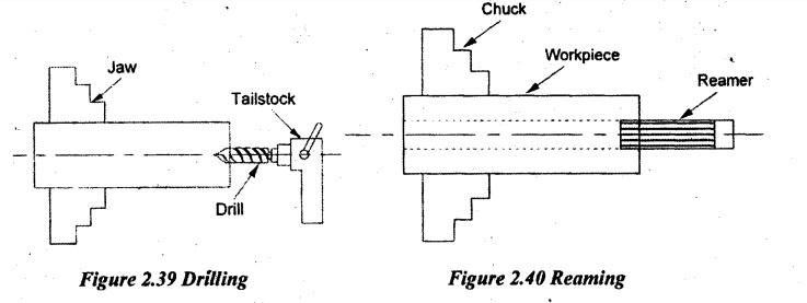
13. Reaming
14. Boring
15. Milling
16. Grinding
17. Tapping
18. Taper Turning
19. Thread Cutting
Manufacturing Technology: Unit II: Turning Machines : Tag: : Turning Machines - Manufacturing Technology - lathe operations
Related Topics
Related Subjects

Manufacturing Technology
ME3493 4th semester Mechanical Dept | 2021 Regulation | 4th Semester Mechanical Dept 2021 Regulation