Theory of Machines: Unit I: Kinematics of Mechanisms
kinematic pair
Kinematics of Mechanisms - Theory of Machines
A kinematic pair is a joint of two links that permits relative motion.
KINEMATIC PAIR
• A kinematic pair is a
joint of two links that permits relative motion.
• When any two links are
connected in such a way that their relative motion is completely or
successfully constrained, they form a kinematic pair.
• Practical examples:
■ In a reciprocating steam engine (Fig.1.1), the kinematic pairs existing are:
(a)
Crank and connecting rod,
(b)
Connecting rod and piston rod, and
(c)
Piston and engine cylinder.
■ The crank and connecting rod of the steam
engine are said to form a kinematic pair, because (i) they are in contact, and
(ii) they have relative motion between them.
1. Classification of Kinematic Pairs
Kinematic
pairs may be classified into many types based on the three considerations, as
shown in Fig.1.10.

I. Kinematic Pairs
Depending upon Relative Motion between Links
1. Sliding (or Prismatic)
Pair (P)
• When two links have a
sliding motion relative to each other, it is known as sliding or prismatic
pair.
• It is designated by the
letter P.
• As shown in Fig.1.11, the
bar 1 is constrained to have a sliding motion relative to bearing 2, forms, a
sliding pair.
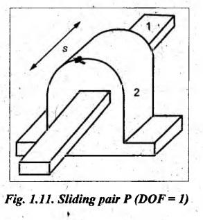
• Since the relative motion
between links 1 and 2 can be expressed by a single co-ordinate '3', therefore
the sliding pair has single degree of freedom.
• Practical examples:
■
Piston and cylinder;
■
Cross-head and guides in a steam engine;
■
Ram and its guides in a shaper;
■
Tail stock on the lathe bed, etc.
2. Turning (or
Revolute) Pair (R)
• When two elements are
connected such that one element revolves around the other, it forms a turning
pair.
• It is designated by the
letter R.
• The turning pair is also
known as a revolute, a hinge or a pin-jointed
pair.
• The shaft 1 with two
collars rotates in a bearing 2, as shown in Fig.1.12, forms a turning pair.
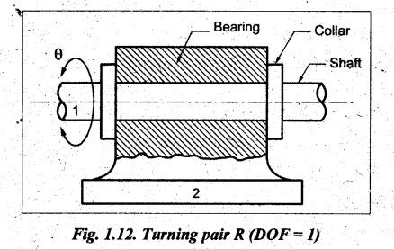
• Since the relative motion
between links 1 and 2 can be expressed by a single co-ordinate 'θ', therefore the
turning pair has a single degree of freedom.
• Practical examples:
■
Lathe spindle supported in the head stock;
■
Crank shaft in a journal bearing in an engine;
■
Cycle wheels turning over their axles;
■
Arbor supported between the arbor support and column of a milling machine; etc.
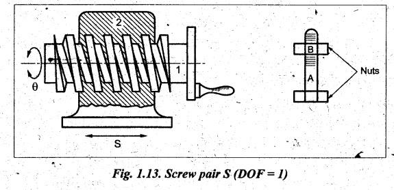
3. Screw (or Helical)
Pair (S)
• In a screw pair, one link
is constrained to have a combination of turning and sliding motion relative to
the other link.
• It is designated by the
letter S.
• In Fig.1.13, the links 1
and 2 form a screw pair.
• Practical examples:
■
Nut and bolt
■
Lead screw of a lathe with nut.
■
Threaded spindle and movable jaw in a bench vice; etc.
• Though the screw pair
allows rotation as well as translation, it has one degree of freedom because
the relative movement between 1 and 2 can be expressed by a single co-ordinate 'θ'
or 's'. These two co-ordinates are related by the relation:  where L is
lead of the screw.
where L is
lead of the screw.
4. Cylindrical Pair (C)
• In a cylindrical pair,
one link is constrained to have a combination of translation and rotation
motion relative to the other link.
• It is designated by the
letter C.
• As shown in Fig.1.14, the links 1
and 2 form a cylindrical pair, as it allows both translation and rotation
motion parallel to the axis of rotation.
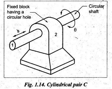
• Unlike screw pair, the
cylindrical pair has two degrees of freedom. Because two independent co-ordinates
's' and 'θ' are required to specify its relative motion.
5. Spherical (or
Globular) Pair (G)
• In a spherical pair, one
link is constrained to swivel in or about the other fixed point.
• It is designated by the
letter G.
• A ball and socket joint
as shown in Fig.1.15, represents the spherical pair.
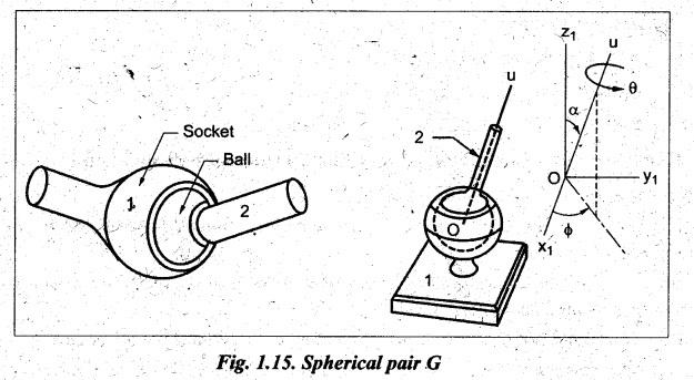
• Since the complete
description of motion of spherical pair requires three independent variables
(two angles α and ϕ) to define the direction Ou and the angle θ of
rotation about Ou. Therefore the spherical pair has three degrees of
freedom.
• Practical examples:
■
Attachment of a car mirror;
■
Ball and socket joint;
■
Pen supporters joint in a pen stand; etc.
6. Rolling Pair
• When one link is free to roll
over the other, it forms a rolling pair.
• A ball and roller bearing
as shown in Fig. 1.16 forms a rolling pair. As shown in Fig.1.16, (i) the ball
and the bearing forms a rolling pair; and (ii) the ball and the shaft also
forms another rolling pair.
• Practical examples:
■
Ball and roller bearings;
■
A lawn mover rolling over a lawn;
■
A road roller rolling over the ground; etc.
II. Kinematic Pairs
Depending upon Nature of Contact between Links
1. Lower Pair
• If a kinematic pair in
motion has a surface or area contact between the two links, it is called a
lower pair.
• It may noted that all
sliding pairs, turning pairs, screw pairs, cylindrical pairs and spherical
pairs form lower pairs.
• Pairs shown in Fig.1.11,
1.12, 1.13, 1.14 and 1.15 are examples of lower pair.
• Practical examples:
Nut and bolt, bolt and socket joint, shaft rotating in bearing, piston reciprocating
in a cylinder, etc.
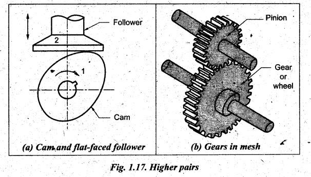
2. Higher Pair
• If a kinematic pair in motion has
a line or point contact between the two links, it is called a higher pair.
• The cam and follower
arrangement shown in Fig.1.17(a) is an example of higher pair, as there is a
line contact between them.
• Practical examples:
■
Cam and flat faced follower, roller bearings, and most gears (Fig.1.17(b)) have
line contact.
■
Cam and knife edge follower, ball bearings, and teeth of skew helical gears
have point contact.
III. Kinematic Pairs
Depending upon Mechanical Arrangements for Constraining Motion
1. Closed (or
Self-clòsed) Pair
• When two links of a pair
are held together mechanically, they constitute a closed pair.
• Practical examples:
All lower pairs are self-closed pairs.
2. Unclosed (or Open
or Force-closed) Pair
• When two links of a pair
are not held together mechanically, they constitute an unclosed pair.
In this case, the contact between the two links is maintained by the forces
exerted by spring and gravity.
• Practical examples:
The cam and follower mechanism (Fig.1.17(a)) forms an unclosed pair.
Theory of Machines: Unit I: Kinematics of Mechanisms : Tag: : Kinematics of Mechanisms - Theory of Machines - kinematic pair
Related Topics
Related Subjects

Theory of Machines
ME3491 4th semester Mechanical Dept | 2021 Regulation | 4th Semester Mechanical Dept 2021 Regulation