Theory of Machines: Unit I: Kinematics of Mechanisms
kinematic link (or element)
Kinematics of Mechanisms - Theory of Machines
A kinematic link, also known as simply a link or an element, is defined as a single part (or an assembly of rigidly connected parts) of a machine which has motion relative to some other part of the machine.
KINEMATIC LINK (OR ELEMENT)
• A kinematic link,
also known as simply a link or an element, is
defined as a single part (or an assembly of rigidly connected parts) of a
machine which has motion relative to some other part of the machine.
• A link need not
necessarily be a rigid body, but it must be a resistant body.
• Thus the essential characteristics
of being a link are:
(i)
It should have relative motion.
(ii)
It must be a resistant body.
• Practical examples:
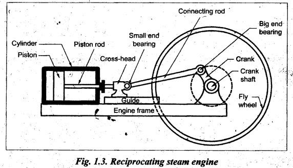
In a reciprocating steam engine" shown in Fig.1.3, the four different
links obtained are:
• Rigid body Vs.
Resistant body
• Rigid body means a body with no
deformation when the required force is transmitted. A body is said to be
resistant if it is capable of transmitting the required force with negligible
deformation.
• It does not necessarily mean that the resistant
bodies should be rigid; they can also be flexible. Practical examples:
Belt, ropes, chains, and oil used in hydraulic brakes are not rigid links, but
they are resistant bodies.
• Working of a reciprocating steam engine: When steam is
admitted into the cylinder, it exerts pressure on the piston. The pressure on
the piston pushes it along the cylinder and the force is transmitted through
the piston rod to the connecting rod, which causes the crank to revolve. At the
point where the piston rod and connecting rod meet, there is a cross head;
cross-head runs to and fro in a guide to prevent the piston rod being broken or
bent crank shaft by the oblique thrusts of the connecting rod. The crank is
keyed to a shaft called crankshaft. The carries the flywheel. Thus in a
reciprocating steam engine, the heat energy of the steam is converted into
rotary motion of crankshaft (i.e., mechanical energy).
• Link 1:
Piston, piston rod and cross-head constitute a first link.
• Link 2:
Connecting rod with big end and small end bearings constitute a second link.
• Link 3:
Crank, crankshaft and flywheel constitute a third link.
• Link 4:
Cylinder, engine frame and main bearings form a fourth link.
• It may be noted that a
link need not to be single part, but it may consist of several parts which are
manufactured as separate units.
• For example, piston,
piston rod and cross-head in steam engine (Fig.1.3) consists of different
parts, but after joining together they do not have relative motion with respect
to each other; therefore they form one link.
1. Types of Links
There
are three types of links as classified in Fig. 1.4 and are presented in Table
1.1.
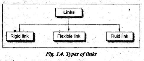
Table 1.1. Classification of links
1. Rigid Link:
• A link which does not
undergo any deformation while transmitting motion is known as a rigid link.
• Practical
examples: Connecting rod and crank-pin in a steam engine; and bed and
spindle of a lathe do not have appreciable deflection and as such they can be
termed as rigid links.
2. Flexible Link:
• A link which is partly
deformed in such a way that it does not affect the transmission of motion is
known as flexible link.
• Practical
examples: Belts, ropes, chains and springs are deformed considerably
while transmitting motion but deformation has no effect on the transmission of
motion.
3. Fluid Link:
• A link which transmits
the motion by fluid pressure or compression is known as fluid link.
• Practical
examples: Fluids used in hydraulic press, hydraulic jack, hydraulic
crane, etc., acts as a link.
Theory of Machines: Unit I: Kinematics of Mechanisms : Tag: : Kinematics of Mechanisms - Theory of Machines - kinematic link (or element)
Related Topics
Related Subjects

Theory of Machines
ME3491 4th semester Mechanical Dept | 2021 Regulation | 4th Semester Mechanical Dept 2021 Regulation