Engineering Graphics: Unit V (a): Isometric Projection
Isometric Projections of objects from their Orthographic Projections
Engineering Graphics (EG)
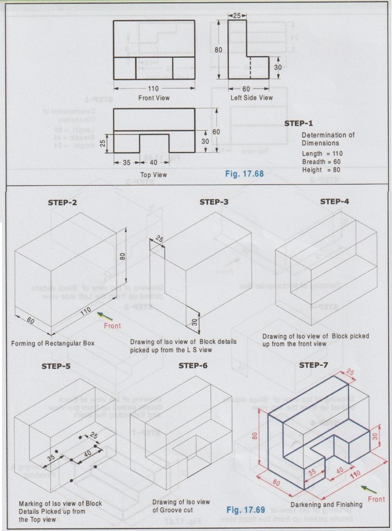
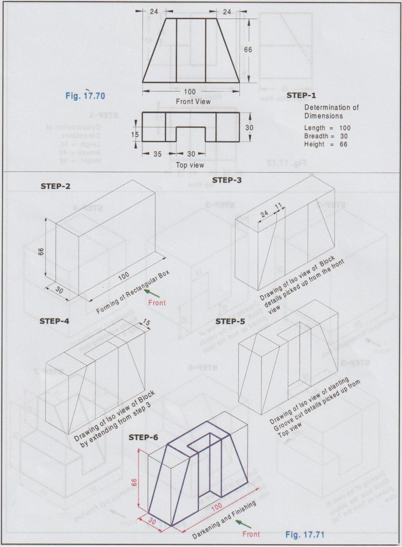
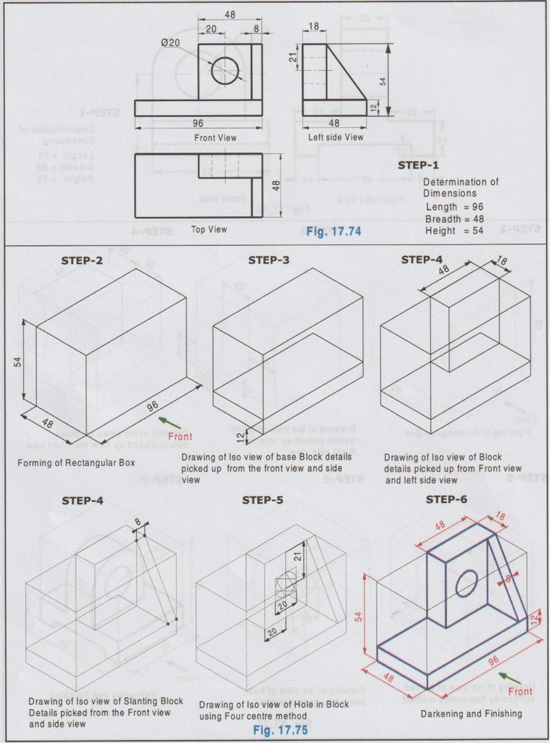
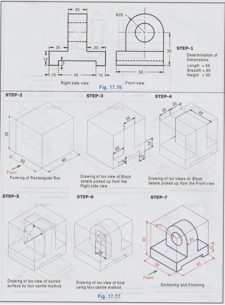
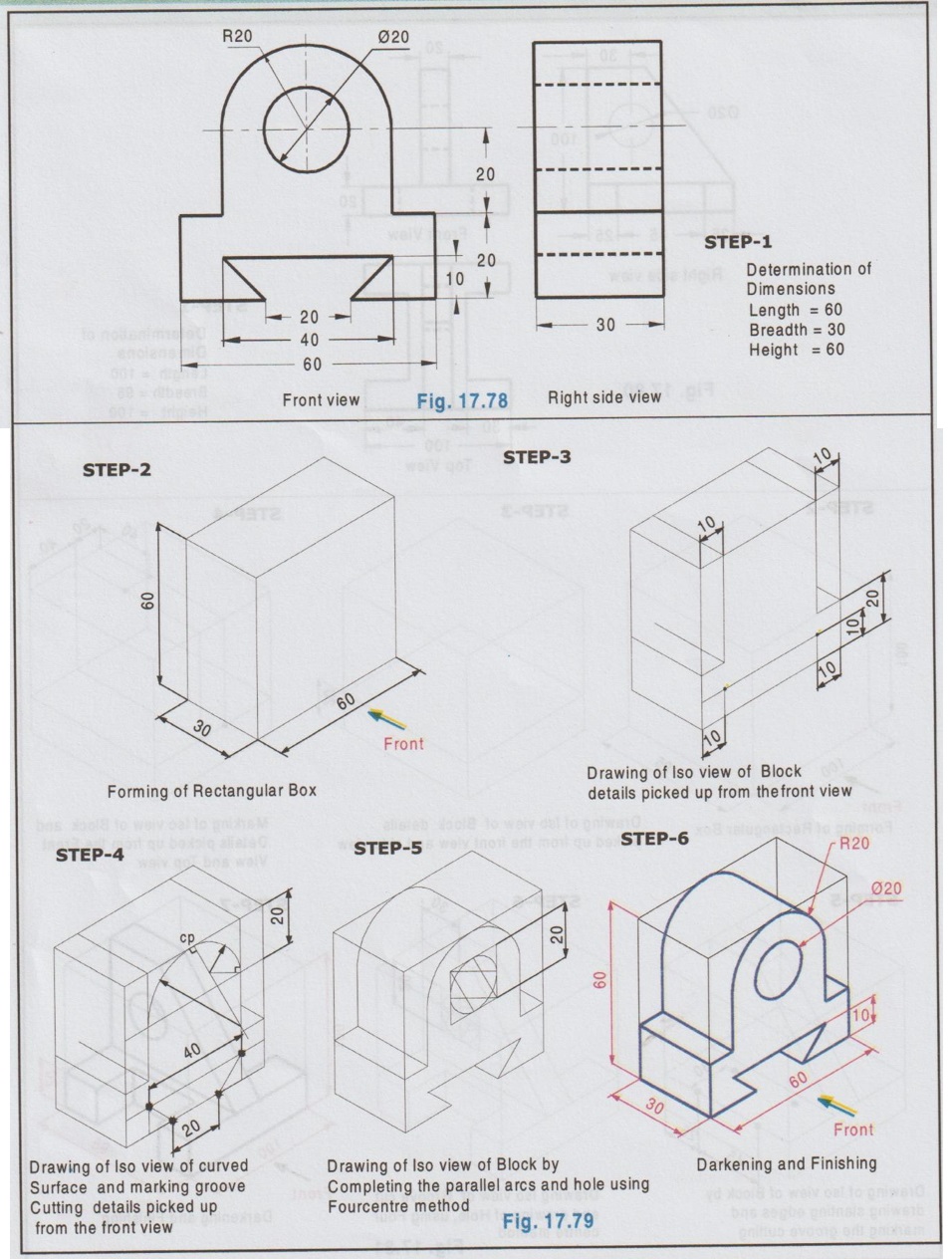
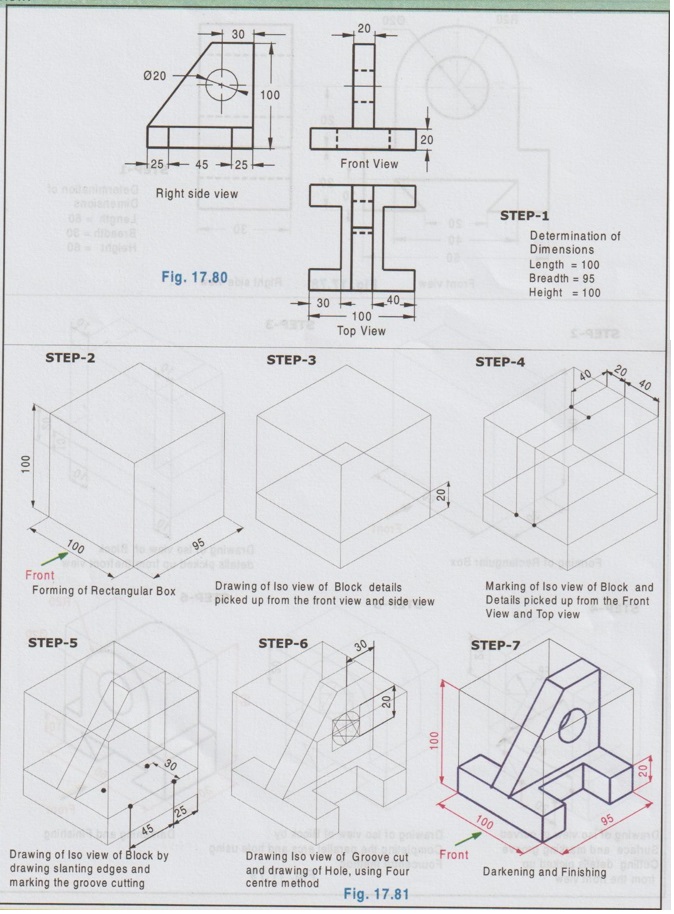
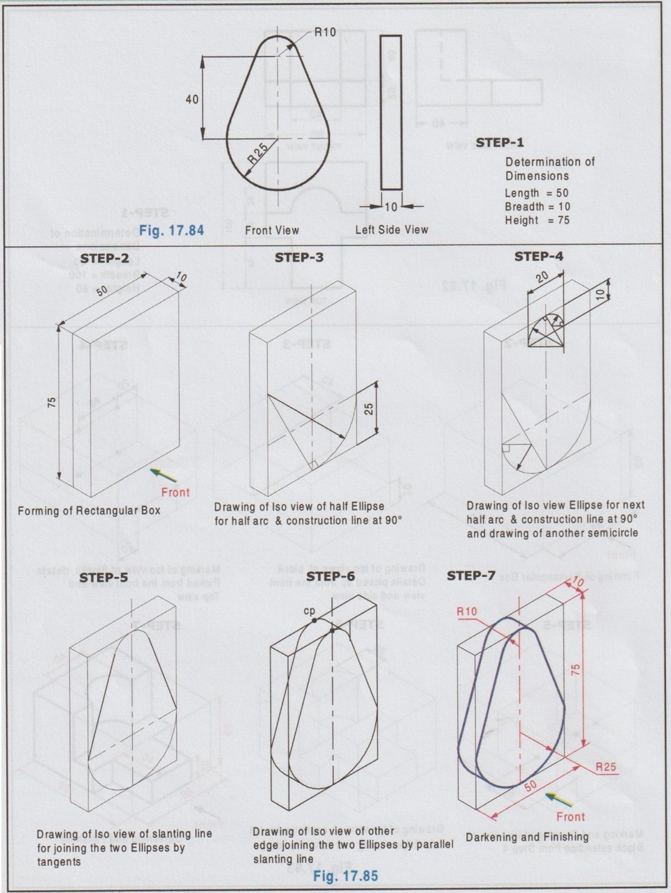
While drawing isometric view from the available multiview orthographic projections, the following points should be followed.
ISOMETRIC PROJECTIONS OF OBJECTS FROM THEIR ORTHOGRAPHIC PROJECTIONS While drawing isometric view from the available multiview orthographic projections, the following points should be followed. 1. It is essential to visualise the shape of object before starting the drawing. 2. The location of the origin of the isometric axes to be fixed in such a way that it shows the maximum information of the object. 3. Box method (or) Offset method can be followed. 4. Front view of the object can be drawn on either left isometric (or) right isometric plane. 5. Length of the object is normally taken on x (or) y axis. 6. The construction lines (drawn as thin lines) to be retained in order to understand the method of drawing. 7. The hidden lines and curves of the object may be shown only if they are necessary. 8. Dimension the object properly. The following examples describe the procedure of drawing isometric projection / view from the given multiview orthographic projections. Example 37: Draw the isometric view of the object, of which orthographic projections are shown in Fig. 17.66. Example 38: For the orthographic projections shown in Fig. 17.68 draw the Isometric view. Example 39: Front view and top view of an object are shown in Fig. 17.70. Draw its isometric view. Example 40: For the orthographic projections shown in Fig. 17.72, draw the isometric view. Example 41: For the orthographic projections shown in Fig. 17.74, draw the isometric view. Example 42: Front view and side view of an object are shown in Fig. 17.76. Draw its isometric view. Example 43 : For the orthographic projections shown in Fig. 17.78, draw the isometric view. Example 44: Front view and right side view of an object are shown in Fig. 17.80. Draw its isometric view. Example 45: For the orthographic projections shown in Fig. 17.82, draw its isometric view. Example 46: For the orthographic projections shown in Fig. 17.84 draw its isometric view. Example 47: For the orthographic projections shown in Fig. 17.86, draw its isometric view. Isometric view is drawn as shown in Fig. 17.87.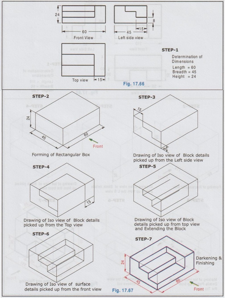


Engineering Graphics: Unit V (a): Isometric Projection : Tag: : Engineering Graphics (EG) - Isometric Projections of objects from their Orthographic Projections
Related Topics
Related Subjects

Engineering Graphics
GE3251 eg 2nd semester | 2021 Regulation | 2nd Semester Common to all Dept 2021 Regulation