Engineering Graphics: Unit V (a): Isometric Projection
Isometric Projection of Truncated Solids
Engineering Graphics (EG)
When a solid is cut by a plane which is inclined to the axis of solid and the portion of solid above the plane is removed, the remaining portion of solid is known as `Truncated solid'.
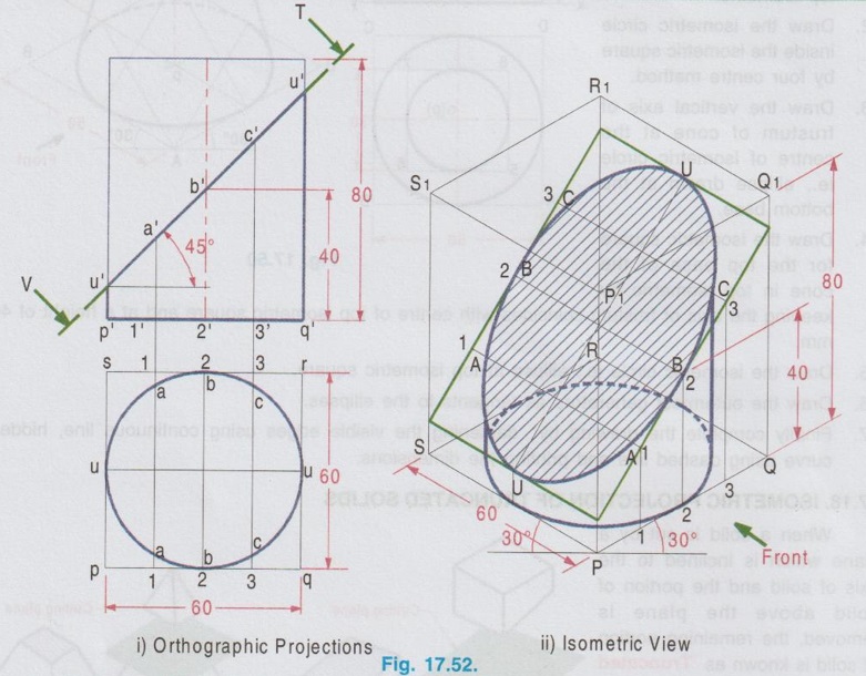
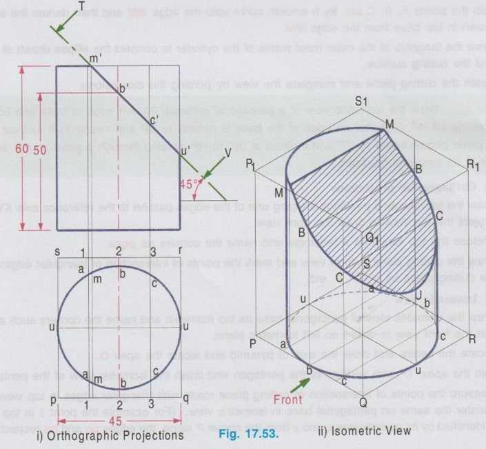
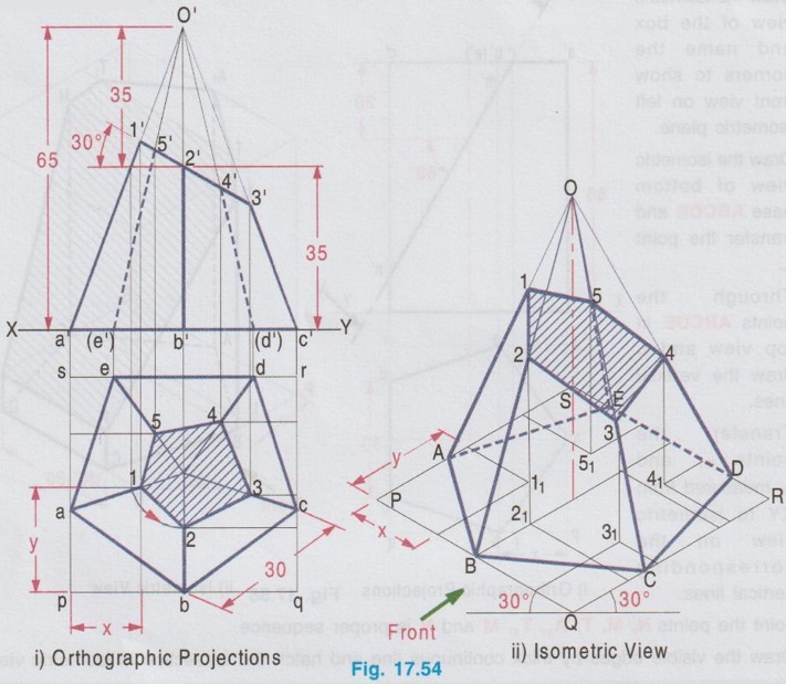
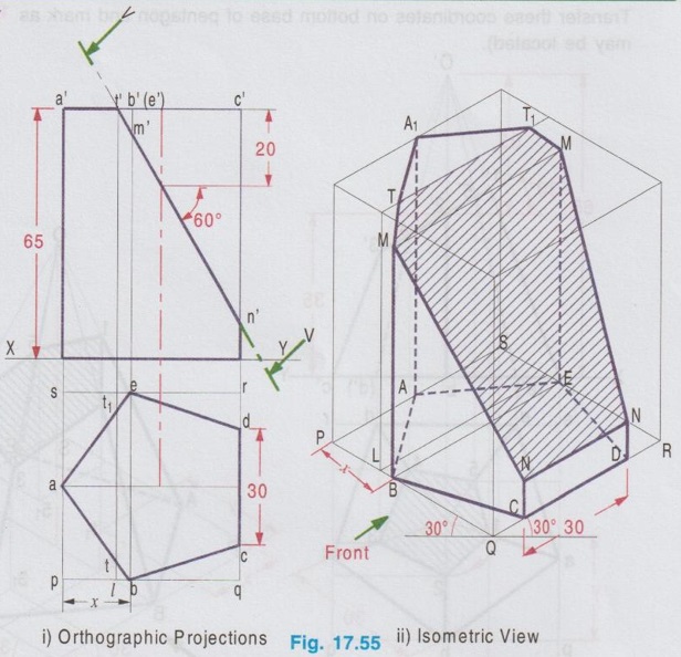
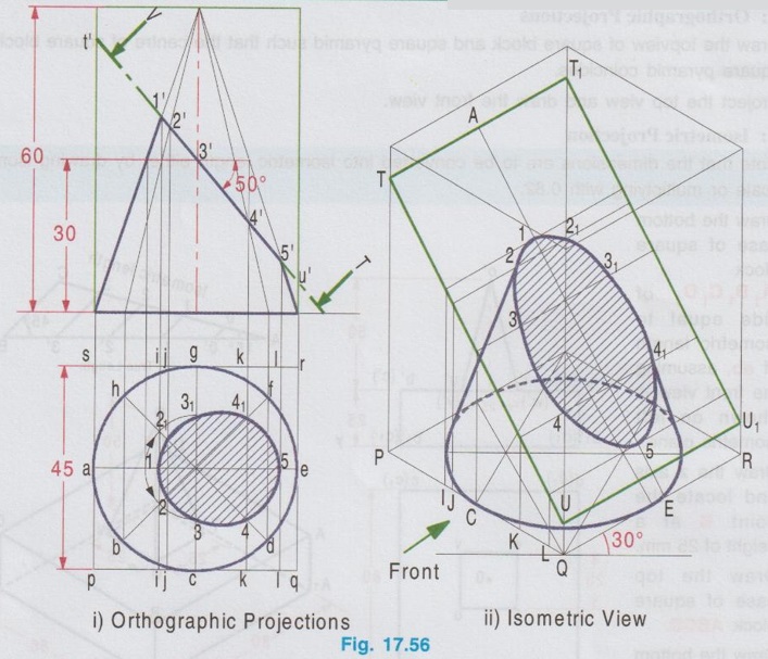
ISOMETRIC PROJECTION OF TRUNCATED SOLIDS When a solid is cut by a plane which is inclined to the axis of solid and the portion of solid above the plane is removed, the remaining portion of solid is known as `Truncated solid'. Isometric projection of truncated solid can be drawn by box method or coordinate method. In box method, after drawing the isometric view of the box, the cutting plane is marked in the box, and the cut surface is drawn on that plane. Where as in coordinate method, the truncated surface is obtained by marking the coordinates of the boundary points from an isometric plane as reference. Isometric projections of truncated solids having uniform cross section (prism and cylinder) and uniformly varying section (pyramid and cone) are presented in the following examples. Example 23: A cylinder of diameter 60 mm base and 80 mm height is resting on its base on HP with its axis perpendicular to HP. A section plane of 45° inclination to HP bisects the axis of the cylinder. Draw the isometric view of the cylinder and show the sectioned surface. Step 1: Orthographic Projections 1. Draw the top view as a circle of diameter 60 mm and front view as a rectangle of height 80 mm. 2. Enclose the circle into a square and name the corners of square as pqrs. 3. Mark the section plane in front view which bisects the axis at an angle of 45° to horizontal. 4. Divide the box pqrs into two equal parts horizontally to cut the circumference of circle at UU. 5. Divide the box pqrs vertically into four equal parts at 1-1, 2-2, 3-3 to cut the circumference of circle at aa, bb and cc respectively. 6. Project these points to section plane and mark the points as 1'(a'), 2'(b') and 3'(c'). Step 2: Isometric View 1. Draw the isometric view of the box with bottom base PQRS and top base P1Q1R1S1 with height 80 mm. 2. Draw the isometric view of circle ie., ellipse at the bottom base to represent the base of the cylinder. 3. The inclined section plane cuts the cylinder to form an ellipse symmetrical about the line uu. Hence draw the isometric view of the section plane in the isometric box and mark the line of symmetry UU on it. 4. Measure the distance P-1 in top view and transfer the same on the side PQ at bottom base of the isometric view of the box from the corner P and draw a vertical line to cut the inclined section plane at 1. 5. Through the point 1 draw a line 1-1 perpendicular to axis of symmetry of inclined section plane UU. 6. Measure the distance a-a in top view and mark the same as A-A on the line 1-1, symmetrical about the line UU. 7. Similarly draw lines 2-2, 3-3 etc. and mark the points B-B, C-C etc. on them. 8. Join all these points by a smooth curve to obtain the sectioned surface as an ellipse. 9. Draw the outermost vertical generators to complete the view of the cylinder. 10. Darken the visible edges by continuous line and hidden curve by dashed line. 11. Hatch the cut section and print the dimensions to complete the drawing. (For obtaining sharp curve divide the circle in top view into 6 equal parts vertically and proceed). Example 24: Draw the isometric view of a truncated cylinder of diameter 45 mm and height 60 mm resting on its base on HP with axis perpendicular to HP. It is cut by a plane perpendicular to VP and inclined at 45° to HP. The plane meets the axis at a height of 50 mm from the bottom base. Step 1: Orthographic Projections 1. Draw the top view as a circle of diameter 45 mm and front view as a rectangle of height 60 mm. 2. Enclose the circle into a square of side 45 mm and name the corners as p, q, r and s. 3. Draw the section plane in front view at an angle of 45° to xy and cutting the axis at 50 mm from base. 4. Divide the square pqrs in top view into two parts horizontally and four parts vertically. Let the ends of horizontal diameter be uv and the vertical division of square cuts the edges parallel to xy at 1-1, 2-2 and 3-3. 5. Let the vertical divisions cuts the circumference of circle at a-a, b-b (ie. 2-2) and c-c. 6. Project the edge of section plane from front view to top view and mark as m-m. Step 2: Isometric View 1. Draw the isometric view of the box and name the edges assuming the left isometric plane is used for showing front view. 2. Draw the isometric view of the base as an ellipse. 3. Measure the distances of the points a, b, c etc. from top view and transfer the same on the bottom base of isometric box. 4. Measure the height of points a', b', c' etc. and transfer the same by offset method. 5. Join the points A, B, C etc. by a smooth curve upto the edge MM and then darken the ellipse drawn in top base from the edge MM. 6. Draw the tangents at the outer most points of the cylinder to connect the ellipse drawn at base and the cutting surface. 7. Hatch the cutting plane and complete the view by printing the dimensions. Example 25: Draw the isometric view of a pentagonal pyramid, 30 mm edge of base and 65 mm height resting on HP such that an edge of the base is parallel to VP and nearer to it and cut by a section plane perpendicular to VP and inclined at 30° to HP passing through a point on the axis at a height of 35 mm from the base. Step 1: Orthographic projections 1. Draw the topview as a pentagon keeping one of the edges parallel to the reference axis XY and Project the top view to draw the front view. 2. Enclose the top view into a rectangle and name the corners as pqrs. 3. Draw the cutting plane in front view and mark the points of intersection of triangular edges with the cutting plane as 1', 2', 3' etc. Step 2: Isometric view 1. Draw the isometric view of pentagonal base as top isometric and name the corners such a way that the front view is drawn on left isometric plane. 2. Locate the centre and draw the axis of pyramid and locate the apex O. 3. Join the apex 'O' with vertices of the pentagon and finish the isometric view of the pentagon. 4. Measure the points of intersection of cutting plane made with triangular edges in top view and transfer the same on pentagonal base in isometric view. (For example the point 1 in top view is identified by its co-ordinates x and y from the corner P along the edges pq and ps respectively. Transfer these coordinates on bottom base of pentagon and mark as 11. Similarly other points may be located). 5. Erect vertical through the points 11, 21, 31 etc. to meet the corresponding slant edges OA, OB, OC etc. at 1, 2, 3 etc. 6. Join these points by straight line and darken the visible edges by continuous line. 7. Hatch the sectioned surface and complete the drawing by printing the dimensions. Example 26: Draw the isometric view of a pentagonal prism of base side 30 mm and axis 65 mm long is resting on the ground on its base with one of the edges of base is perpendicular to VP. The prism is cut by a plane perpendicular to VP, inclined at 60° to HP and intersect the axis at 20mm from the top. Step 1: Orthographic Projections 1. Draw the topview as a pentagon keeping one of the edges perpendicular to the reference axis XY and enclose the top view into a rectangle pqrs. 2. Project the top view to draw the front view. Draw the cutting plane in front view cutting the axis at 20 mm from top base, cutting the top base at t' and the vertical edges projected through the corners b and e at m', c and d at n'. 3. Project the point t' to plan to cut the edges ab and ae at t and t1 respectively and the side of square pq at l. Step 2: Isometric view 1. Draw the isometric view of the box and name the corners to show front view on left isometric plane. 2. Draw the isometric view of bottom base ABCDE and transfer the point L. 3. Through the points ABCDE in top view and L draw the vertical lines. 4. Transfer the points m' and n' measured from XY to isometric view on the corresponding vertical lines. 5. Joint the points N, M, T, A1, T1, M and N is proper sequence. 6. Draw the visible edges by thick continuous line and hatch the cutsection in isometric view. Example 27: Draw the isometric view of a cone of base diameter 45mm and height 60mm rests on its base in HP when it is cut by a plane perpendicular to VP, inclined at 50° to HP and meeting the axis at 30 mm above the base. Step 1: Orthographic Projections 1. Draw the topview and front view. 2. Enclose the top view into a square pqrs and the front view into a rectangle. 3. Divide the circumfence of circle in topview into eight equal parts and draw generators. 4. Draw the cutting plane in front view to meet the vertical edges of rectangle enclosed for front view at t' and u' and the generators at 1', 2, 3', 4' and 5'. 5. Draw the vertical projectors through 1', 2', 3' etc., to the topview and locate the corresponding points 1, 2, 21, 3, 31, 4, 41 and 5 and the side of square pq at i j c k l as shown in figure. Join the points 1, 2, 3 ..... 21, 1 in a proper sequence which represents the apparent section. (Construction of apparent section of a cone is already explained in chapter 15) Step 2: Isometric view 1. Draw the isometric box and the cutting plane TU assuming the left isometric plane is used for front view. 2. Draw the isometric view of the base of cone as an ellipse. 3. Transfer the points i, j, c, k and l to the bottom base of isometric box. 4. Draw vertical lines through these points to meet the cutting line TU and then draw the lines parallel to QR side of isometric box. 5. Locate the points 1, 2, 21 etc. on the corresponding projectors such that the distances from symmetric axis AE are equal to the respective distances 1, 2, 21 etc. measured in topview from the line ae. 6. Join these points in a proper sequence by freehand curve and show the extreme generators of cone by continuous thick line. Hatch the cut section.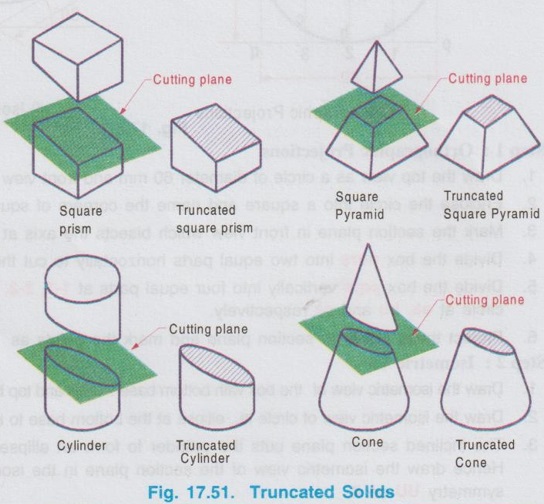
Engineering Graphics: Unit V (a): Isometric Projection : Tag: : Engineering Graphics (EG) - Isometric Projection of Truncated Solids
Related Topics
Related Subjects

Engineering Graphics
GE3251 eg 2nd semester | 2021 Regulation | 2nd Semester Common to all Dept 2021 Regulation