Engineering Graphics: Unit V (a): Isometric Projection
Isometric Projection of Straight line
Engineering Graphics (EG)
Isometric lines which are parallel to the isometric axes are directly drawn by measuring the dimensions.
ISOMETRIC PROJECTION OF STRAIGHT LINE (i) Isometric Line Isometric lines which are parallel to the isometric axes are directly drawn by measuring the dimensions. Draw the isometric axes and then draw the isometric lines of the object parallel to the isometric axes. A straight line drawn parallel to isometric axes is shown in Fig. 17.11. (ii) Non Isometric Line Non-Isometric lines, which are not parallel to any of the isometric axes are drawn by locating their ends and then by joining them. For example let the isometric projection of a line AB of length l inclined at θ to x axis shown in Fig. 17.12 (i) to be drawn in isometric view. (a) Right Isometric (Fig. 17.2 ii) 1. Draw a horizontal axis of short length and locate the point A. 2. Draw right side Isometric axis AO inclined at 30° to horizontal and mark the point O such that AO is equal to a'o' in front view. 3. Draw vertical isometric axis OB passing through O and mark the point B such that OB is equal to o'b' in front view. 4. Join the points A and B by a straight line which is the required isometric view of the given line. Note that In isometric projection the length of non isometric line AB and angle made with horizontal are not equal to the true dimensions l and θ respectively. (b) Left Isometric (Fig. 17.2 (iii) ) Follow the procedure as given for Right isometric but constructing the isometric axis AO on the left side of point A, at an angle of 30°.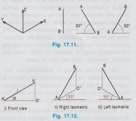
Engineering Graphics: Unit V (a): Isometric Projection : Tag: : Engineering Graphics (EG) - Isometric Projection of Straight line
Related Topics
Related Subjects

Engineering Graphics
GE3251 eg 2nd semester | 2021 Regulation | 2nd Semester Common to all Dept 2021 Regulation