Engineering Graphics: Unit V (a): Isometric Projection
Isometric Projection of solids containing non-isometric lines
Engineering Graphics (EG)
Isometric projection of solids containing non-isometric lines like prism, pyramid, cylinder are drawn by two methods.
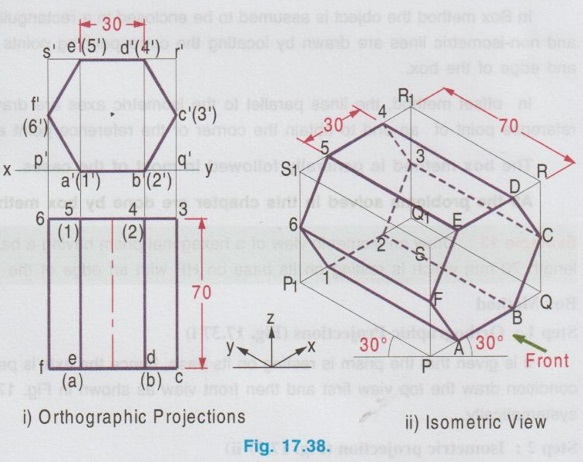
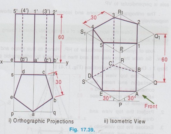
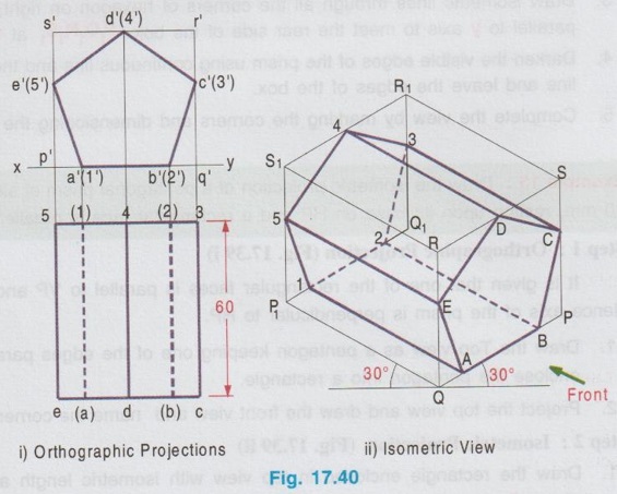
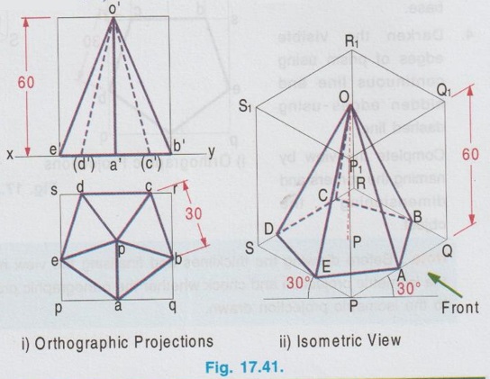
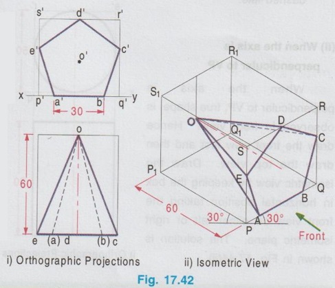
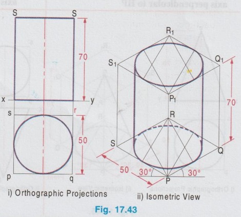
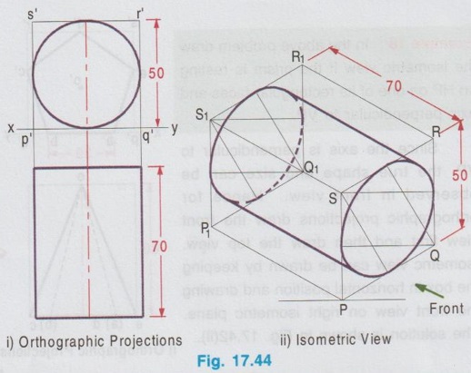
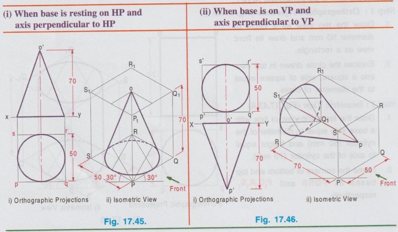
ISOMETRIC PROJECTION OF SOLIDS CONTAINING NON-ISOMETRIC LINES Isometric projection of solids containing non-isometric lines like prism, pyramid, cylinder are drawn by two methods. (i) Box Method and (ii) Offset (or Co-ordinate method) In Box method the object is assumed to be enclosed in a rectangular box and both the isometric and non-isometric lines are drawn by locating the corresponding points of contact with the surfaces and edge of the box. In offset method, the lines parallel to the isometric axes are drawn from every corner or the reference point of an end to obtain the corner or the reference point at the other end. The box method is generally followed in most of the cases. All the problems solved in this chapter are done by box method. Example 13: Draw an isometric view of a hexagonal prism having a base with 30 mm side and axis length 70 mm which is resting on its base on HP with an edge of the base parallel to VP. Box Method Step 1: Orthographic Projections (Fig. 17.37 i) It is given that the prism is resting on its base, hence the axis is perpendicular to HP. With this condition draw the top view first and then front view as shown in Fig. 17.37(i) and name the corners systematically. Step 2: Isometric projection (Fig. 17.37 ii) 1. Enclose the hexagon in top view into a square pqrs. 2. Draw the isometric view of square pqrs in top view as top isometric keeping the point P as origin. 3. Mark the points A, B, C, D, E and F in the isometric view such that PA = pa, PB = pb, PF = pf, QC = qc etc. 4. Draw the isometric lines through all the corners of PQRS to a height of 70 mm. and complete the top of box P1Q1R1S1. 5. Draw the isometric lines parallel to z axis through all the points A,B,C,D,E and F to cut the edges of Rhombus P1Q1R1S1. 6. Mark the points of intersection of these isometric lines with top base as 1, 2, 3, 4, 5 and 6. 7. Join the points 1, 2, 3, 4, 5 and 6 in a sequence and obtain the isometric view of the hexagonal prism. Example 14: In the above lugne problem draw the isometric anio view of hexagonal prism if it is resting on HP on one of its rectangular faces with axis perpendicular to VP. Step 1: Orthographic projections (Fig. 17.38 i) 1. Draw the front view as a hexagon such that one of the rectangular faces is resting on HP. 2. Enclose the hexagon into a square p'q'r's'. 3. Project the front view for the top view and name the corners accordingly. Step 2: Isometric View (Fig. 17.38 ii) 1. Draw the isometric view of the box PQRS, P1Q1R1S1 taking the dimensions from the front view and top view. Here the front view is taken on right isometric plane. 2. Construct the hexagon on the right isometric plane such that PA = p'a', PB = p'b', PF = p'f' etc. 3. Draw isometric lines through all the corners of hexagon on right isometric plane A, B, C etc. parallel to y axis to meet the rear side of the box P1Q1R1S1 at 1, 2, 3 etc. 4. Darken the visible edges of the prism using continuous line and the hidden edges using dashed line and leave the edges of the box. 5. Complete the view by marking the corners and dimensioning the object. Example 15: Draw the isometric projection of a pentagonal prism of side of base 30 mm and height 60 mm, resting upon its base on HP and a rectangular face is parallel to VP. Step 1: Orthographic Projection (Fig. 17.39 i) It is given that one of the rectangular faces is parallel to VP and the base is resting on HP. Hence axis of the prism is perpendicular to HP. 1. Draw the Top view as a pentagon keeping one of the edges parallel to reference line xy and got nerf bas enclose the pentagon into a rectangle. 2. Project the top view and draw the front view and name the corners in top view and front view. Step 2: Isometric Projection (Fig. 17.39 ii) 1. Draw the rectangle enclosed in top view with isometric length as top isometric keeping the corner P as origin. 2. Construct the box with bottom base PQRS and top base P1Q1R1S1. 3. Mark the points ABCDE in bottom base and draw vertical lines to locate the points 1 2 3 4 5 in top base. 4. Darken the visible edges of prism using continuous line and hidden edges using dashed line. 5. Complete the view by naming the corners and dimensioning the object. Note: Before drawing the thicklines and finalising the view mark the direction of front view in the isometric projection and check whether the orthographic projections drawn earlier are correct nd to the isometric projection drawn. Example 16: In the above problem draw the isometric projection of pentagonal prism if the prism is resting on one of its rectangular faces on HP and axis perpendicular to VP. Since the axis is perpendicular to VP the true shape and size can be observed in front view. Hence draw the front view and then top view for orthographic projections. Isometric projection can be drawn in the same procedure explained above but keeping the box in horizontal position for the observer since the axis is perpendicular to VP. The orthographic projections and isometric projection are shown in Fig. 17.40 (i) and (ii) respectively. Example 17: Draw the isometric view of a pentagonal pyramid having a base with 30 mm side and 60 mm long axis when its axis is perpendicular to HP. Axis of pyramid is perpendicular to HP. Hence its true shape and size can be observed in top view. So draw the top view first and then front view for orthographic projections. Step 1: Orthographic Projections (Fig. 17.41 i) 1. Draw the top view as a pentagon and name the corners as a, b, c, d and e assuming an edge of base is parallel to VP. 2. Project the top view and draw the front view. 3. Enclose the top view into a rectangle and name the corners as p, q, r and s. Step 2: Isometric View (Fig. 17.41 ii) 1. Draw the rectangle enclosed by the pentagon in topview as rhombus isometric. 2. Mark the points A, B, C, D and E in the bottom base which represents the corners of pentagon such that PQ = pq, PE = pe etc., 3. Mark the mid point of top base of the box as O1. 4. Join the corners of pentagon A, B, C, D and E with O1. 5. Darken the visible edges with continuous line and hidden edges with dashed line. Example 18: In the above problem draw the isometric view if the prism is restingce" on HP on one of its rectangular faces and axis perpendicular to VP. Since the axis is perpendicular to VP, the true shape and size can be observed in front view. Hence for orthographic projections draw the front view first and then draw the top view. Isometric view can be drawn by keeping the box in horizontal position and drawing the front view on right isometric plane. The solution is shown in Fig. 17.42(ii). Example 19: Draw an isometric view of a cylinder with 50 mm base diameter and 70 mm long axis (i) When the axis is perpendicular to HP (ii) When the axis is perpendicular to VP. i) When the axis is perpendicular to HP. Step 1: Orthographic Projections (Fig. 17.43 i) 1. Draw the top view as a circle of diameter 50 mm and draw its front view as a rectangle. 2. Enclose the circle drawn in top view into a square, side of square equal to the diameter of circle. Step 2: Isometric View (Fig. 17.43 ii) 1. Draw the isometric view of box with a base side equal to diameter of the cylinder (50 mm) and height equal to axis of the cylinder (70 mm). 2. Name the corners of bottom and top bases as PQRS and P1Q1R1S1 respectively. 3. Inscribe an ellipse on the square base PQRS and P1Q1R1S1 using four centre method. 4. Draw two common tangents to two ellipse (ie., draw two isometric lines parallel to z axis joining the ellipse drawn on top and bottom bases by joining the points on the outermost points on the circumference of ellipse). 5. Darken the visible edges of the cylinder with continuous line and hidden half of the ellipse with dashed line. (ii) When the axis is perpendicular to VP When the axis is perpendicular to VP, true shape is observed in front view. Hence draw the front view first and then draw the top view. Draw the isometric view by keeping the box in horizontal position taking the front view on either left or right isometric plane. The solution is shown in Fig. 17.44(ii). Example 20: Draw an isometric view of a cone with 50 mm base diameter and 70 mm long axis (i) when the base is resting on HP with axis perpendicular to HP and (ii) when the base is on VP with axis perpendicular to VP.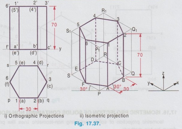
Engineering Graphics: Unit V (a): Isometric Projection : Tag: : Engineering Graphics (EG) - Isometric Projection of solids containing non-isometric lines
Related Topics
Related Subjects

Engineering Graphics
GE3251 eg 2nd semester | 2021 Regulation | 2nd Semester Common to all Dept 2021 Regulation