Engineering Graphics: Unit V (a): Isometric Projection
Isometric Projection of sectioned solids
Engineering Graphics (EG)
When a solid is cut by a plane perpendicular to the axis and the portion of solid above the plane is removed, the remaining portion of solid is known as sectioned solid.
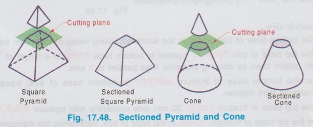
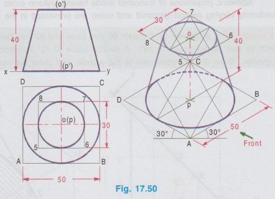
ISOMETRIC PROJECTION OF SECTIONED SOLIDS When a solid is cut by a plane perpendicular to the axis and the portion of solid above the plane is removed, the remaining portion of solid is known as sectioned solid. If a solid is having uniform cross section throughout its length like prism and cylinder, then the sectioned solid is also a prism or cylinder having same cross section but reduced height. If a solid is having uniformly varying cross section like pyramid and cone, then the sectioned solid is frustum of pyramid or frustum of cone. In such cases the cross section of solid at the section does not remains the same as that of the base. Hence for the sectioned solids draw the orthographic projections first and then draw the required isometric projection / isometric view. The procedure of drawing the isometric projection of frustum of pyramid and frustum of cone are explained by the following examples. Example 21: Draw an isometric view of the frustum of a hexagonal pyramid having 35 mm base side, 20 mm top side and 70 mm long axis, resting on its base on the H.P. with an edge of the base parallel to the VP. It is given that the frustum of pyramid is resting on its base on HP, hence the axis is perpendicular to HP, and the true shape is observed in top view. When the frustum of pyramid is seen from top, two hexagons of side 35 mm and 20 mm, which are concentric are seen. By projecting these two hexagons we get front view. Step 1: Orthographic Projections 1. Draw the top view of bottom base as hexagon of side 35 mm, keeping an edge of the base parallel to xy. Name the corners as a, b, c, d, e and f. 2. Enclose the hexagon into a square and name the corners as p, q, r and s. 3. Draw the top view of top base as hexagon of side 20 mm such that its centre coincides with the centre of outer hexagon and name the corners as 1, 2, 3, 4, 5 and 6. 4. Enclose the inner hexagon into a square and name the corners as t,u,v and w. 5. Project the top view and draw the front view. Step 2: Isometric view 1. Draw the bottom base of box PQRS in top isometric, taking measurement from top view. 2. Draw the top base of box P1Q1R1S1 parallel to bottom base PQRS at a height of 70 mm and join with bottom base by drawing isometric lines parallel to z axis. 3. Inscribe the bottom base of frustum ABCDEF in bottom base of box, transferring the measurements from topview. 4. Draw the top base of frustum TUVW, 20 mm side concentric with topbase P1Q1R1S1 5. Inscribe the top base of frustum 123456 in top base of box, transferring the measurements from ens topview. 6. Join the corresponding corners of hexagon drawn in top and bottom bases which is the required isometric view. 7. Finally complete the drawing by printing the dimensions as shown in Fig. 17.49 (ii). Example 22: Draw the isometric projections of a frustum of a cone of base diameter 50 mm, top diameter 30 mm and height 40 mm which is resting on its base on HP with its axis perpendicular to HP. Step 1: Orthographic Projections (Fig. 17.50 i) 1. Since the axis is perpendicular to HP the true shape can be observed in top view. Hence draw the top view of frustum of cone as two concentric circles of diameters 50 mm and 30 mm. 2. Project the top view and draw the front view. 3. Enclose the circles in top view into squares. ABCD and 5678. Step 2: Isometric Projection (Fig. 17.50 ii) Using isometric scale, 1. Draw the isometric square for the base of the cone in top isometric. 2. Draw the isometric circle inside the isometric square by four centre method. 3. Draw the vertical axis of frustum of cone at the centre of isometric circle ie., ellipse drawn at the bottom base. 4. Draw the isometric square for the top base of the cone in top isometric by keeping the axis of frustum coincides with centre of top isometric square and at a height of 40 mm. 5. Draw the isometric circle ie., ellipse at top isometric square. 6. Draw the outermost generators as tangents to the ellipses. 7. Finally complete the drawing by darkening the visible edges using continuous line, hidden curve using dashed line and printing the dimensions.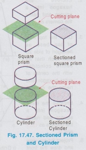

Engineering Graphics: Unit V (a): Isometric Projection : Tag: : Engineering Graphics (EG) - Isometric Projection of sectioned solids
Related Topics
Related Subjects

Engineering Graphics
GE3251 eg 2nd semester | 2021 Regulation | 2nd Semester Common to all Dept 2021 Regulation