Engineering Graphics: Unit V (a): Isometric Projection
Isometric Projection of plane figures of straight edges
Engineering Graphics (EG)
Since a plane figure is a two dimensional object, only two isometric axes are used to draw its isometric view.
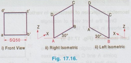
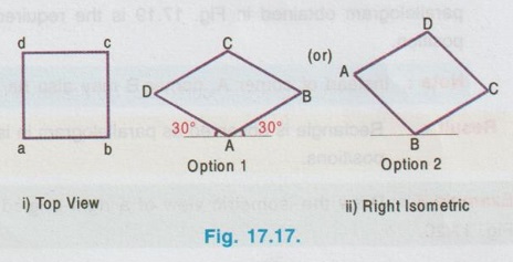
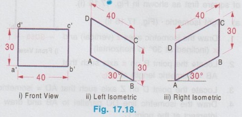
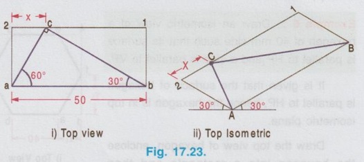
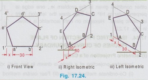
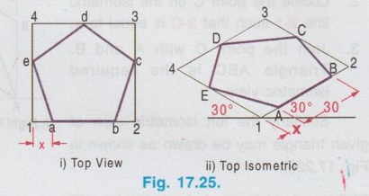
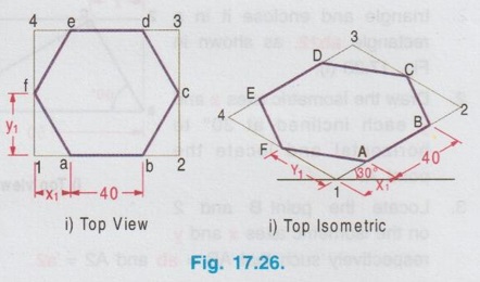
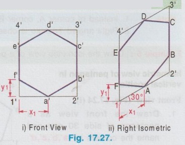
ISOMETRIC PROJECTION OF PLANE FIGURES OF STRAIGHT EDGES Since a plane figure is a two dimensional object, only two isometric axes are used to draw its isometric view. The isometric view or Isometric projection of a plane figure can be drawn either in vertical (or) horizontal position. Example 1: Draw the isometric projection of a square of size 50 mm in vertical position. To draw the isometric projection of square in vertical position draw the front view of square first as shown in Fig. 17.16 (i). a) Right Isometric (Fig. 17.16 ii) 1. Draw the isometric axes z (vertical) and x (inclined at 30° to horizontal) 2. Locate the point B on x axis such that AB = isometric length of a'b'. 3. Locate the point D on Z axis such that AD = isometric length of a'd'. 4. Draw the isometric line DC parallel to AB and draw the isometric line BC parallel to AD to intersect at the point C. 5. The Rhombus ABCD obtained is the required isometric projection of square. Note: Square is observed as Rhombus in Isometric projection. b) Left Isometric (Fig. 17.16 iii) Follow the same procedure given for Right isometric view but taking the isometric axes y and z. Note that the corner A is taken as origin for Right isometric where as the corner B is taken as origin for left isometric. If isometric view of square is required follow the same procedure given for isometric projection but taking the true length instead of isometric length. Example 2: Draw the isometric projection of a square of size 40 mm in horizontal position. To draw the isometric projection of a square in horizontal position draw the top view of the square first as shown in Fig. 17.17(i). Top Isometric 1. Draw the isometric axes x and y each inclined at 30° to horizontal. 2. Locate the point B on x axis such that AB isometric length of ab. 3. Similarly locate the point D on y axis such that AD = isometric length of ad. 4. Draw the isometric lines DC and BC to intersect at C. 5. Now the Rhombus ABCD obtained is the required isometric projection of square in horizontal position. Note : 1. Instead of corner A, the corner B may also be taken as origin as shown in option 2. 2. To draw the isometric view use true length instead of isometric length. 3. In horizontal position also, square is observed as Rhombus in Isometric view. Example 3: Draw the isometric projection of a rectangle 40 mm × 30 mm in (i) Vertical and (ii) horizontal positions. Isometric projection of Rectangle in vertical position Draw the front view of rectangle as shown in Fig. 17.18 (i). Left Isometric (Fig. 17.18 ii) 1. Locate the origin B and locate the points A and C on y and z axes such that AB = isometric length of a'b' and BC = isometric of length of b'c'. 2. Draw isometric lines AD and CD parallel to BC and BA respectively to intersect at the point D. Parallelogram BADC is the required left isometric of the given rectangle in vertical position. Similarly the right isometric can be drawn as shown in Fig. 17.18(iii). Isometric projection of Rectangle in Horizontal position Draw the top view of rectangle as shown in Fig.17.19 (i). Top Isometric (Fig. 17.19 ii) 1. Draw the isometric axes x and y through the origin each a inclined at 30° to horizontal and locate the points D and B on y and x axes such that AD = isometric length of ad. and AB isometric length of ab. 2. Draw isometric lines DC and BC parallel to AB and AD respectively to intersect at C. The parallelogram obtained in Fig. 17.19 is the required isometric view of rectangle in horizontal position. Note: Instead of corner A, corner B may also be taken as origin. Result : Rectangle is observed as parallelogram in isometric view both in vertical and horizontal positions. Example 4: Draw the isometric view of a right angled triangle, front view of which is shown in Fig. 17.20. Enclose the given right angled triangle in a rectangle and name the corners of rectangle as a',b', 1' and 2' as shown in Fig. 17.21. Measure the distance 2' - c' in front view as x. Right Isometric (Fig. 17.22 i) 1. Draw the isometric view of rectangle taking x and z axes as shown in Fig. 17.22 (i). 2. Locate the point C on the isometric line 2-1 such that 2-C is equal to x. 3. Join the point C with A and B. Triangle ABC is the required isometric view. Similarly the left isometric view of given triangle may be drawn as shown in Fig. 17.22(ii). 1. Draw the top view of the triangle and enclose it in a rectangle ab12. as shown in Fig. 17.23(i). 2. Draw the Isometric axes x and y each inclined at 30° to horizontal and locate the point A. 3. Locate the point B and 2 on the isometric axes x and y respectively such that AB = ab and A2 = a2. 4. Construct the parallelogram AB12 by drawing isometric lines 2-1 and B-1 to intersect at 1. 5. Locate the point C on isometric line 2-1 such that 2-C = 2-c on top view. 6. Join the point C with A and B. Triangle ABC is the required isometric view. Note : 1. Instead of corner A, corner B may also be taken as origin 2. Right angled Triangle is observed as oblique triangle in Isometric view. Example 5: Draw the isometric view of a pentagon of side 30 mm in (i) vertical and (ii) horizontal. Front view (Fig. 17.24 (i)) 1. Draw the front view as a pentagon of side 30 mm and name the corners as a',b',c', d' and e'. 2. Enclose the pentagon in a rectangle 1', 2', 3', 4' as shown in Fig. Right Isometric (Fig. 17.24 ii) It is to be noted that only the edge AB is an isometric line and the other lines are non-isometric lines. Hence other corners are to be located by offset method and then joined by straight lines as as shown in Fig. 17.24. Similarly the left isometric can be drawn as shown in Fig. 17.24 (iii) by taking the point 2 as origin. Top view (Fig. 17.25 i) 1. Draw a pentagon of side 30 mm and name the vertices as a, b, c, d and e. 2. Enclose the pentagon in a rectangle and name the corners as 1, 2, 3 and 4. Top isometric is drawn as shown in Fig. 17.25(ii). Example 6: Draw an isometric view of a hexagon of 40 mm side such that its surface is parallel to HP and a side is parallel to VP. It is given that the surface of hexagon is parallel to HP, hence the hexagon is in top isometric plane. Draw the top view of hexagon, enclose the hexagon into a rectangle and then construct the required isometric view as shown in Fig. 17.26. Example 7: Draw an isometric view of a hexagon of 40 mm side such that its surface is parallel to VP and a side is perpendicular to HP. It is given that the surface of hexagon is parallel to VP, hence the hexagon is to be drawn in vertical position. Draw the front view of hexagon first satisfying the other condition given in the problem ie., one edge is perpendicular to HP and then draw the left (or) right y1] isometric plane. Hexagon on right isometric is shown in Fig. 17.27.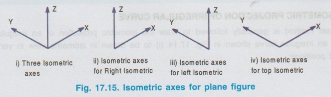

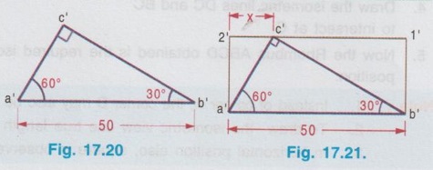
Right angled triangle in vertical position.

Right angled triangle in horizontal position
Isometric view of pentagon in vertical position
Isometric view of pentagon in horizontal position
Engineering Graphics: Unit V (a): Isometric Projection : Tag: : Engineering Graphics (EG) - Isometric Projection of plane figures of straight edges
Related Topics
Related Subjects

Engineering Graphics
GE3251 eg 2nd semester | 2021 Regulation | 2nd Semester Common to all Dept 2021 Regulation