Engineering Graphics: Unit V (a): Isometric Projection
Isometric Projection of plane figures of curved boundary
Engineering Graphics (EG)
Isometric projection of a circle is drawn in two methods namely (i) Co-ordinate method and (ii) Four centre method
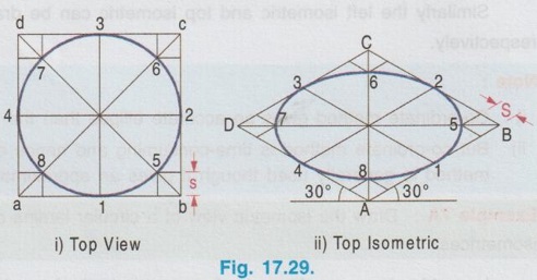
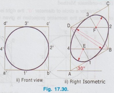
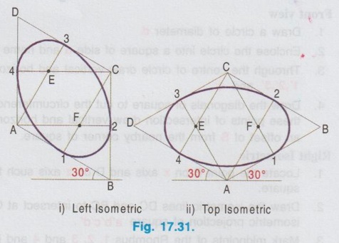
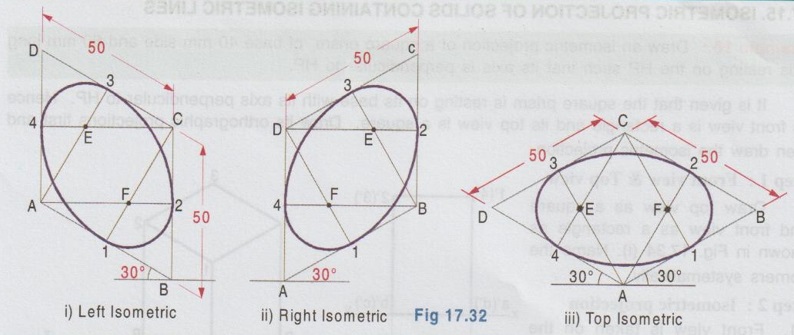
ISOMETRIC PROJECTION OF PLANE FIGURES OF CURVED BOUNDARY Isometric projection of a circle is drawn in two methods namely (i) Co-ordinate method and (ii) Four centre method (i) Co-ordinate Method Consider a circle of diameter 'd', the right isometric of which is required. Step by step procedure of constructing the isometric projection is given below: 1. Draw circle of diameter d. 2. Enclose the circle into a square of side d and name the corners of square as a', b',c' and d'. 3. Through the centre of circle draw vertical and horizontal diameters to cut the circumference at 1', 2', 3' and 4'. 4. Draw the diagonals of square to cut the circumference of circle at 5',6′,7′ and 8' and through these points of intersection draw vertical and horizontal offsets to cut the sides of square with an offset of S from the nearby corner of square. 1. Locate the point B on x axis and D on z axis such that AB = AD = isometric length of side of square. 2. Draw the isometric lines DC and BC to intersect at C. Now ABCD is a Rhombus which is the isometric projection of square a'b'c'd'. 3. Mark midpoints of the Rhombus 1, 2, 3 and 4 and join 1 and 3 and 2 and 4. 4. Draw the diagonals of Rhombus. To locate the point 5: i) Mark the offset s (isometric length of offset in front view) on the adjacent sides of Rhombus with respect to the corner B. ii) Draw horizontal and vertical offset lines to intersect the diagonal at 5. 5. Similarly locate the points 6, 7 and 8. Join the points 1, 2, 3 etc. with a smooth curve in the form of an ellipse which is the required isometric projection. Left isometric of circle may be drawn as shown in Fig. 17.28 (iii). Similarly the top view of circle and top isometric arc given in Fig. 17.29 (i) and (ii) respectively. Result: Circle is observed as ellipse in isometric projection in both vertical and horizontal position. (ii) Four Centre Method : Front view 1. Draw the front view of the circle. 2. Enclose the circle into a square of vertices a',b',c' and d' and mark the mid points of sides as 1',2',3' and 4'. Right Isometric 1. Construct the Rhombus ABCD which is the isometric projection of square a', b', c' and d' Rhombus has two axes, major axis passing a' through the corners A and C and minor axis passing through the corners D and B. 2. Locate the mid point of sides of Rhombus as 1, 2, 3 and 4. 3. Consider the corners connecting the minor axis ie., corners B and D. Join the points 3 and 4 with B and join the points 1 and 2 with D. 4. Let the lines B4 and D1 intersect at E and the lines D2 and B3 intersect at F. 5. Taking E as centre and E4 (or E1) as radius draw an arc 1-4. 6. Then taking F as centre and F3 (or F2) as radius draw an arc 2-3. 7. Taking B as centre and B3 (or B4) as radius draw an arc 3-4. 8. Finally taking D as centre and D1 (or D2) as radius draw an arc 1-2. The ellipse obtained which is passing through the points 1, 2, 3 and 4 is the required right isometric. Similarly the left isometric and top isometric can be drawn as shown in Fig. 17.31 (i) and (ii) respectively. Note : i) Co-ordinate method gives an accurate ellipse than the ellipse by four centre method. ii) But co-ordinate method is time-consuming and hence due to ease of construction four centre method is generally used though it gives an approximate solution. Example 7A: Draw the isometric view of a circular lamina of 50 mm diameter in left, right and top isometrices. Isometric views are drawn by four centre method as shown in Fig. 17.32. Example 8: Draw isometric view of a semicircular plane with 60 mm diameter in vertical and horizontal positions. i) Right Isometric 1. Draw the Rhombus ABCD of side 60 mm and locate mid point of sides 1,2,3 and 4. 2. Join B and 3 and D and 2. 3. Let B3 and D2 to intersect at E. 4. With E as centre and E3 as radius draw an arc 2-3. 5. With B as centre and B3 as radius draw an arc 3-4. 6. Join the points 4 and 2 with a straight line. The isometric view of semicircle in right isometric is shown in Fig. 17.33(i). Similarly the left isometric and top isometric are drawn as shown in Fig. 17.33(ii) and (iii) respectively. Example 9: Draw an isometric view of a quadrant of radius 40 mm in vertical and horizontal positions. Isometric view of a quadrant of circle can be drawn as explained in article 17.11. (i) Isometric Projection of a Circle

Front view
Right Isometric

Engineering Graphics: Unit V (a): Isometric Projection : Tag: : Engineering Graphics (EG) - Isometric Projection of plane figures of curved boundary
Related Topics
Related Subjects

Engineering Graphics
GE3251 eg 2nd semester | 2021 Regulation | 2nd Semester Common to all Dept 2021 Regulation