Engineering Graphics: Unit V (a): Isometric Projection
Isometric Projection of Irregular Curve
Engineering Graphics (EG)
Off-set method is generally followed to draw the isometric projection of an irregular curve.
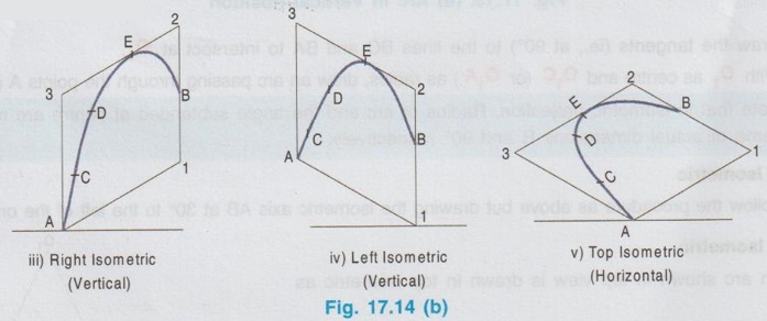
ISOMETRIC PROJECTION OF IRREGULAR CURVE Off-set method is generally followed to draw the isometric projection of an irregular curve. Consider an irregular curve shown in Fig. 17.14 (i) to be drawn in isometric view in vertical and horizontal positions. 1. Locate some reference points on the given curve ab at c, d, e and f. 2. Through the reference points a, b, c, etc. draw vertical and horizontal lines so that the given curve ab is fit into a rectangle. 3. Mark the successive offsets as x1, x2 .... etc. horizontally and y1, y2 …. etc. vertically as shown in fig. 17.14 (ii). (Offsets need not be of equal length) 4. Mark the corners of rectangle as a, 1, 2, and 3.) 1. Draw the right isometric plane on the isometric axes A-1 and A-3 and construct the Rhomus A123. 2. Mark the offsets x1, x2 etc. and y1, y2 …. etc. on isometric axes A-1 and A-3 respectively. 3. Locate the points of intersection as reference points C, D, E and F. 4. Join the points with a smooth curve which is the required isometric view (shown in Fig. 17.14 iii). Similarly the given irregular curve can be drawn in left isometric and top isometric as shown in eenil ondemoel erf Fig. 17.14 (iv) and Fig. 17.14 (v) respectively.Marking the Reference Points

Isometric Projections
Engineering Graphics: Unit V (a): Isometric Projection : Tag: : Engineering Graphics (EG) - Isometric Projection of Irregular Curve
Related Topics
Related Subjects

Engineering Graphics
GE3251 eg 2nd semester | 2021 Regulation | 2nd Semester Common to all Dept 2021 Regulation