Engineering Graphics: Unit V (a): Isometric Projection
Isometric Projection of combination of solids
Engineering Graphics (EG)
This section deals with the isometric projection / view of combination of solids having two (or) more solids arranged one above an another (or) removed one from an another.
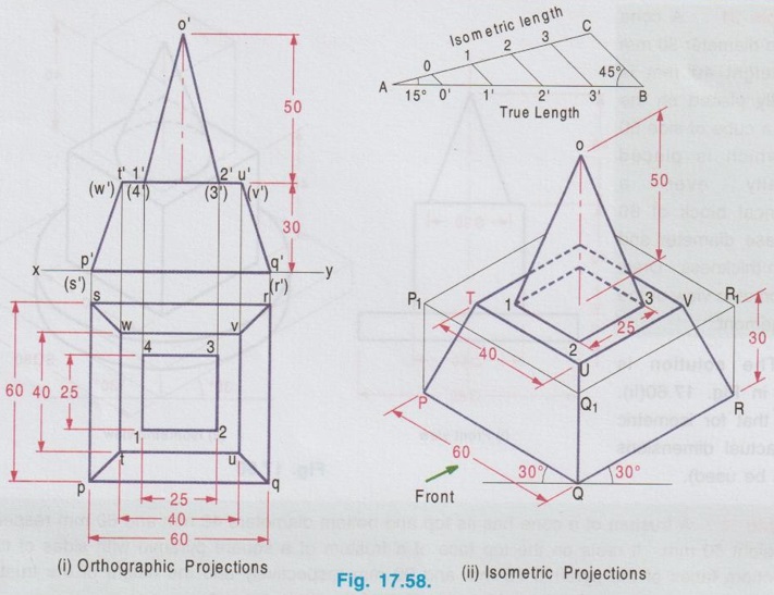
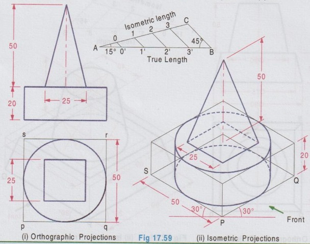
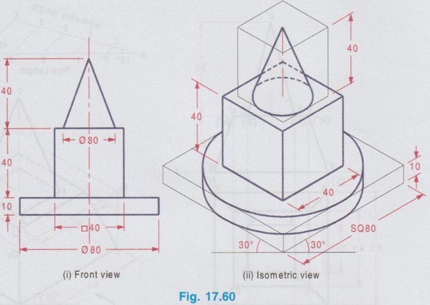
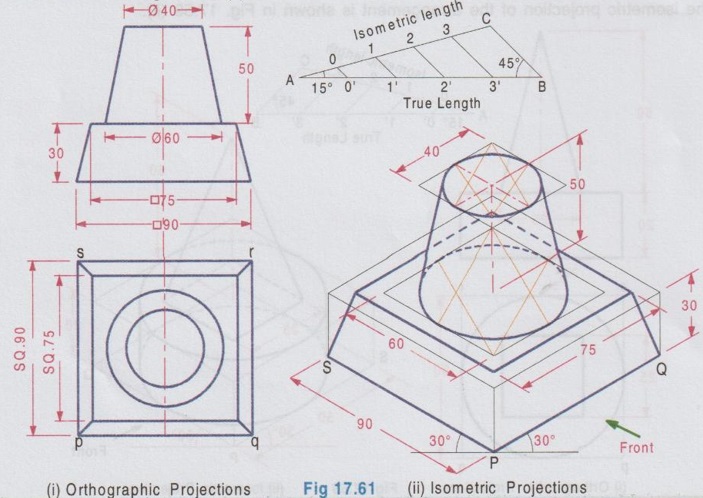
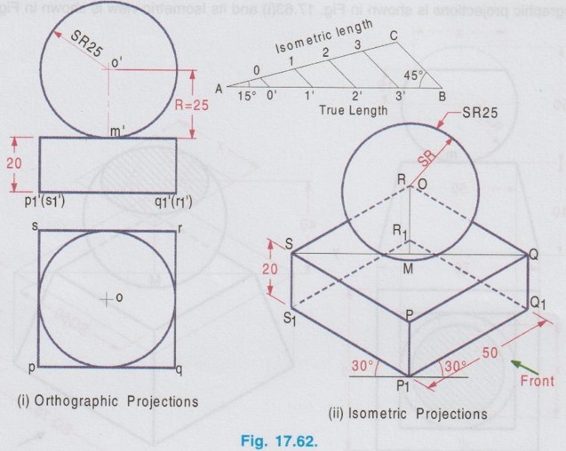
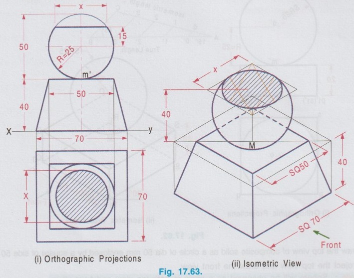
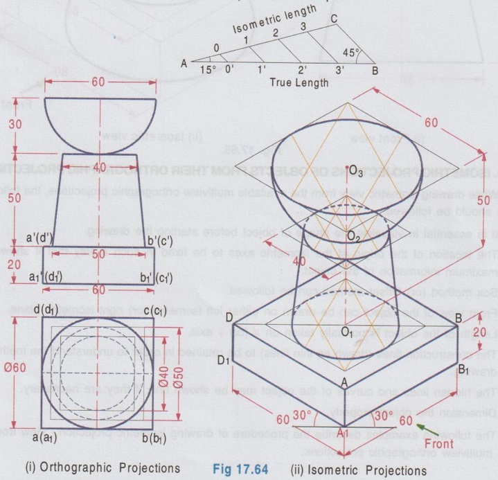
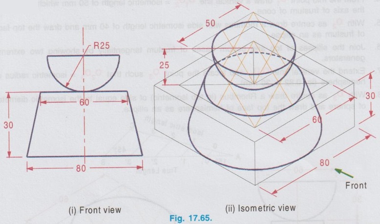
ISOMETRIC PROJECTION OF COMBINATION OF SOLIDS This section deals with the isometric projection / view of combination of solids having two (or) more solids arranged one above an another (or) removed one from an another. The drawing procedure for the isometric projection of a combination of two (or) more solids is similar to that of individual solids. Example 28: A square pyramid of base of 25 mm side and 50 mm long axis rests centrally over a square block of 80 mm base side and 25 mm thickness. Draw the isometric projection of the arrangement. The orthographic projections are shown in Fig. 17.57(i) and the isometric projection of the arrangement is shown in Fig. 17.57(ii). Step 1: Orthographic Projections 1. Draw the topview of square block and square pyramid such that the centre of square block and square pyramid coincides. 2. Project the top view and draw the front view. Step 2: Isometric Projection Note that the dimensions are to be converted into isometric length either by drawing isometric scale or multiplying with 0.82. 1. Draw the bottom base of square block A1 B1 C1 D1 of side equal to isometric length of ab, assuming the front view is shown on left isometric plane. 2. Draw the z axis and locate the point B at a height of 25 mm. 3. Draw the top base of square block ABCD. 4. Draw the bottom base of square pyramid of side equal isometric length of tu such that the centre coincides with the centre point of top base ABCD. 5. Draw the z axis through the centre point of base of pyramid and locate the point O at a height of isometric length of axis of pyramid. 6. Join the point O with the corners of pyramid base TUVW. 7. Darken the visible edges with continuous line and hidden edges with dashed line and finally etub complete the drawing by printing the dimensions.) Example 29: In the above problem if the square pyramid is placed above a trapezoidal block of top and bottom bases of 40 mm and 60 mm sides respectively with thickness 30 mm, draw the isometric projection of the arrangement. Draw the top view as two concentric squares 40 x 40 mm and 60 x 60 mm, corners are joined by inclined lines which shows the tapered surface then draw the base of square pyramid 25 x 25 mm centre of which coinciding with centre of concentric squares drawn. Project the topview to draw front view and then draw isometric projection as shown in Fig. 17.58(ii). Example 30: In the above problem if the square pyramid is placed above a circular disc of 50 mm diameter and 20 mm thickness, draw the isometric projection of the arrangement. The isometric projection of the arrangement is shown in Fig. 17.59 (ii). Example 31 : A cone of base diameter 30 mm and height 40 mm is centrally placed on the top of a cube of side 50 mm which is placed centrally over cylindrical block of 80 mm base diameter and 10 mm thickness. Draw the isometric view of the arrangement. The solution is given in Fig. 17.60(ii). (Note that for isometric view actual dimensions are to be used). Example 32: A frustum of a cone has its top and bottom diameters 40 mm and 60 mm respectively and height 50 mm. It rests on the top face of a frustum of a square pyramid with sides of the top and bottom faces of the pyramid 75 mm and 90 mm respectively and the height of the frustum of pyramid is 30 mm. Draw the isometric projection of the arrangement. The orthographic projections of the arrangement is shown in fig. 17.61(i) and its isometric projection is shown in Fig. 17.61 (ii). Example 33: A sphere of radius 25 mm is placed centrally on a square slab of side 50 mm and thickness 20 mm. Draw the isometric projection of this composite solid. Step 1: Orthographic Projections 1. Draw the top view of composite solid as a circle of dia 50 mm enclosed by a square of side 50 mm. 2. Project the top view and draw the front view. Note: Sphere will be observed as a circle in both top view and front view. 3. Let the point of contact of sphere and square slab be m'. Step 2: Isometric Projection 1. Draw the isometric projection of the slab with bottom base P1Q1R1S1 and top base PQRS in top isometric using isometric lengths. 2. Join the points Q and S (ie. Diagonal QS) and locate the mid point, M which is the midpoint of the top face of the isometric projection of the slab. 3. Draw a vertical line through the point M and locate the point 'O' on it such that OM = the isometric length of o'm' in front view. ie, the isometric length of Radius R. 4. With O as centre and radius R = 25 mm (ie. actual radius) draw a circle to represent the isometric projection of the sphere. (Note that the circle does not pass through the point M). Note: For isometric view, with O as centre and Radius equal to 25/0.82 (ie. actual radius divided by 0.82) draw a circle to represent the isometric view of the sphere. In this case also the circle will not pass through the point M. 5. Darken the visible edges with continuous line and hidden edges with dashed line. 6. Finish the drawing by printing the dimensions. Example 34: A sphere of 25 mm diameter is cut by a section plane at a distance of 15 mm from its centre. It is surmounted with its cut surface at the top, over a frustum of a square pyramid with a 70 mm base side, 50 mm top side and 40 mm height. Draw the isometric view of the arrangement. Orthographic projections is shown in Fig. 17.63(i) and its Isometric view is shown in Fig. 17.63(ii). Example 35: A square prism of base side 60 mm, height 20 mm is resting on the ground with one of its sides parallel to VP. A frustum of cone of 50 mm bottom base diameter, 40 mm top base diameter and 50 mm height is centrally placed over the prism. A hemisphere of 30 mm radius is centrally placed over the frustum of cone. Draw the isometric projection of the arrangement. Note: The isometric projection of the arrangement can be directly drawn starting from the square prism placed at the bottom. However it is suggested to draw the orthographic projections (either free hand sketch or to scale) to visualise the arrangement and also to check the final drawing with its orthographic projections. Step 1: Orthographic projections Front view : 1. Draw the vertical axis of the arrangement and draw the front view of square prism as a rectangle of size 60 × 20 mm. 2. Draw the front view of frustum of cone as a trapezium placed above the prism. 3. Draw the front view of hemisphere as a semicircle, placed above the frustum of cone keeping the horizontal diameter of semicircle parallel to the ground. Top view: Project the front view and draw the top view and name the corners accordingly. Step 2: Isometric Projections 1. Draw the isometric projection of the prism (using isometric length) 2. Draw the major diagonal of rhombus of the top face of the prism and locate its mid point O1. 3. Construct a Rhombus for bottom base of frustum of cone with side of isometric length of 50 mm and draw the bottom base as an ellipse. Side of Rhombus is equal to the base diameter of frustum of cone. 4. From the mid point O1 draw a vertical line O1 O2 = isometric length of 50 mm which represents the axis of frustum of cone. 5. With O2 as centre draw a rhombus with side isometric length of 40 mm and draw the top face of frustum as an ellipse. 6. Join the ellipses of top and bottom bases of frustum tangentially by showing two extreme generators. 7. Extend the vertical line O1 O2 and locate the point O3 such that O2 O3 = isometric radius of hemisphere (ie. 0.82 × 30 mm). 8. With O3 as centre draw a Rhombus (in top isometric) of side equal to the isometric diameter of sphere and draw the top face of hemisphere as an ellipse. 9. With O3 as centre and radius equal to the semi-major axis of ellipse representing the top face of hemisphere draw a semicircle which shows the bottom curvature of hemisphere. Example 36: A Hemisphere of 50 mm diameter rests centrally with its flat surface at the top over a frustum of cone of 80 mm base diameter, 60 mm top diameter and 30 mm height. Draw the isometric view of the arrangement. Front view of the arrangement is shown in Fig. 17.65(i) and its isometric view is shown in Fig. 17.65(ii). 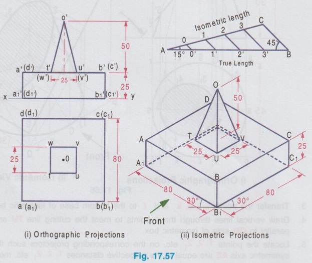
Engineering Graphics: Unit V (a): Isometric Projection : Tag: : Engineering Graphics (EG) - Isometric Projection of combination of solids
Related Topics
Related Subjects

Engineering Graphics
GE3251 eg 2nd semester | 2021 Regulation | 2nd Semester Common to all Dept 2021 Regulation