Engineering Graphics: Unit V (a): Isometric Projection
Isometric Projection and Isometric view
Useful Points to Note
It was explained earlier that when an object is tilted at a particular angle with respect to the vertical art plane and observed from front, its dimensions will be observed lesser than the actual dimensions.
ISOMETRIC PROJECTION AND ISOMETRIC VIEW It was explained earlier that when an object is tilted at a particular angle with respect to the vertical art plane and observed from front, its dimensions will be observed lesser than the actual dimensions. It was found that the actual length is foreshortened by 0.816 times in isometric projection. Hence for isometric projection each and every measurement (other than the non-isometric lines) is reduced to 0.816 times and marked. (Isometric scale may also be used). To avoid the difficulty in determining the fore- shortened lengths, the fore-shortening of the lengths is neglected and the isometric projection can be drawn directly using the true length of the edges along the isometric axes. Thus the Isometric drawing drawn with the actual dimensions is known as "Isometric view". It is noted that the isometric view of an object is larger than the isometric projection of the object. An object drawn in both Isometric projection and Isometric view is shown in Fig. 17.10. Whether the drawing is prepared in Isometric view (or) Isometric projection, while dimensioning only the actual dimensions are to be marked. Isometric view is generally Prefered due to ease of construction and advantage of measuring the dimensions directly from the drawing. 1. If not specified in the problem, draw the Isometric view with true scale. 2. Isometric view has drawn with reference to isometric axes, vertical and two inclined axes each at 30° with horizontal. 3. Three Isometric axes form the three isometric planes namely left, right and top. 4. All the dimensions (actual dimensions) are marked along the isometric axes. 5. If the dimensions are more, proper reduced scale may be adopted. 6. If the drawing is prepared in Isometric projection, draw the isometric scale near by the drawing to indicate the isometric projection. 7. Either Box method (or) Offset method (or) Combination of both may be followed to draw the isometric view. 8. Select the origin of isometric axes and orientation of isometric axes such a way to show the maximum details of the object. 9. Generally the front side of the object is taken towards left (or) towards right. 10. The edges of isometric projection (or) isometric view are named using capital letters. Constructional methods of isometric projections of lines, plane figures, solid figures and three dimensional objects are presented in the following articles. The procedure can be very well applied for Isometric view also. 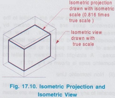
Useful Points to Note:
Engineering Graphics: Unit V (a): Isometric Projection : Tag: : Useful Points to Note - Isometric Projection and Isometric view
Related Topics
Related Subjects

Engineering Graphics
GE3251 eg 2nd semester | 2021 Regulation | 2nd Semester Common to all Dept 2021 Regulation