Theory of Machines: Unit I: Kinematics of Mechanisms
inversions of single slider-crank chain
Kinematics of Mechanisms - Theory of Machines
From a single slider-crank chain, four different inversions can be obtained by fixing its four links one at a time in turn.
INVERSIONS OF SINGLE SLIDER-CRANK CHAIN
• From a single
slider-crank chain, four different inversions can be obtained by fixing its
four links one at a time in turn.
• Table 1.5 shows the
inversions of single slider-crank mechanism and their important applications.
Table 1.5. Inversion of single slider-crank chain and their
applications
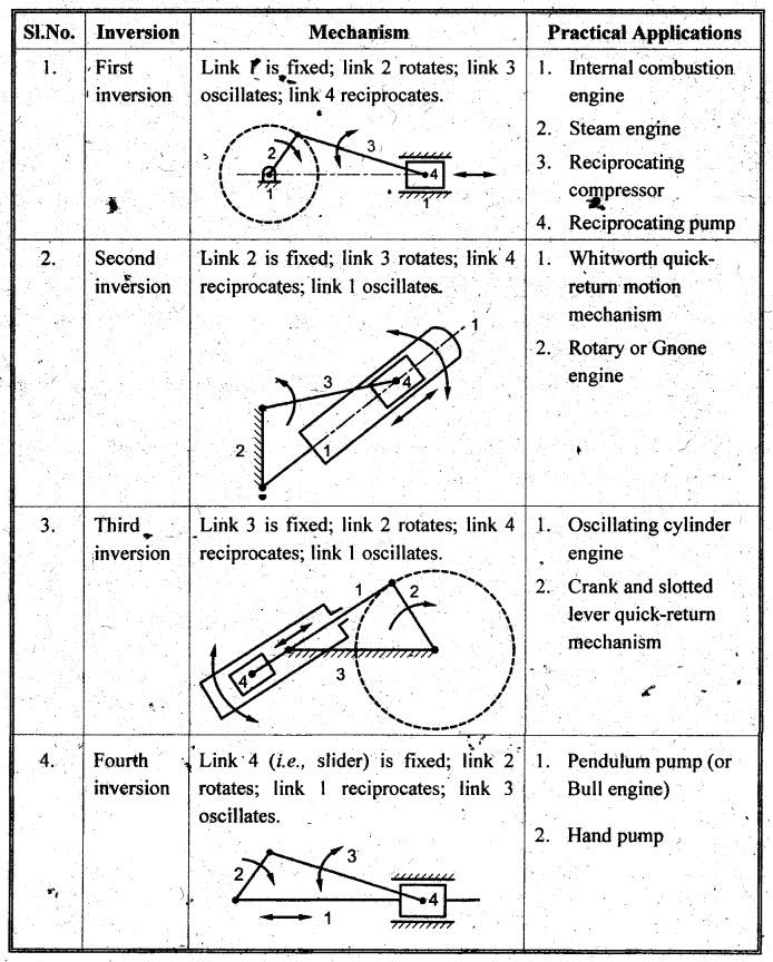
1. First Inversion
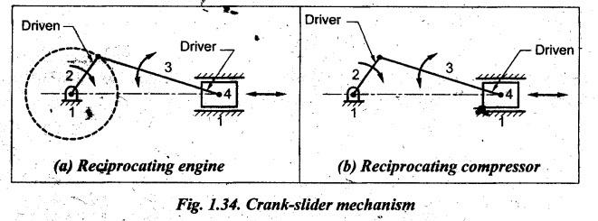
• First inversion is
obtained when the link 1 (i.e., frame) is fixed and links 2 and 4 are made the
crank and the slider respectively, as shown in Fig.1.34. The mechanism thus
obtained is known as crank-slider mechanism.
• Applications:
1. Reciprocating engine
(a)
Internal combustion engine
(b)
Steam engine
2.
Reciprocating compressor
3.
Reciprocating pump
1. Reciprocating
Engine and Reciprocating Compressor
• In both reciprocating
engine and reciprocating compressor, the link 1 (i.e., frame) is fixed.
• In reciprocating engine
(i.e., in IC engine/steam engine), the link 4 (i.e., the slider) is the driver
and the link 2 (i.e., crank) becomes the driven, as shown in Fig. 1.34(a).
• In reciprocating
compressor/reciprocating pump, the link 2 (i.e., the crank) is the driver and
the link 4 (i.e., slider) becomes the driven, as shown in Fig. 1.34(b).
2. Second Inversion.
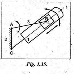
• Second inversion is
obtained by fixing the link 2 (i.e., crank) of a slider-crank chain.
• As shown in Fig.1.35,
when the link 2 is fixed, then the link 3 along with the slider at its end B
becomes a crank. This makes link 1 to rotate about O along with the slider
which also reciprocates on it.
Applications:
1.
Whitworth quick-return mechanism, and
2.
Rotary engine.
1. Whitworth
Quick-Return Mechanism
• Whitworth quick-return
mechanism is used in shaping and slotting machines to cut metals. The forward
stroke cuts the metals whereas the return stroke is idle. Also the return
stroke is quicker than the forward stroke
• In this mechanism, link 2
(i.e., crank) is fixed, link 3 rotates, link 4 reciprocates and link 1
oscillates as shown in Fig.1.36. The link 3 along with its slider (link 4)
rotates in a circle about B. By doing so, the link 1 rotates about A along with
the slider which reciprocates on link 1. On the other end of the link 1, there
is a point D where link 5 is connected. The other end of link 5 is connected to
the ram and tool (link 6). The point D rotates in a circle about point A.
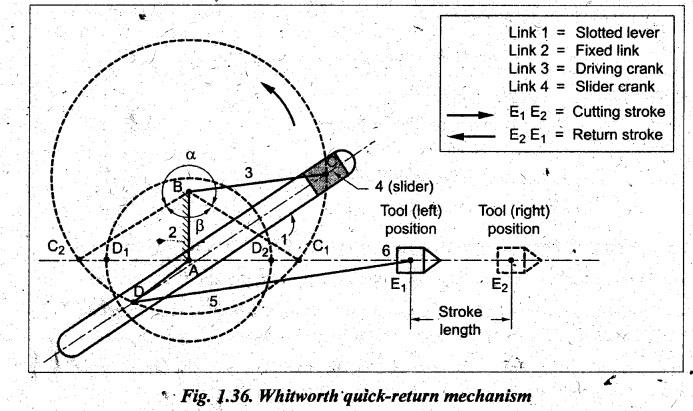
• Forward (or cutting) stroke:
Initially, let the slider 4 be at point C1, then the point D will be
at D1 and hence the tool will be in its extreme left position. As
the crank (link 3) rotates counter-clockwise from BC1 to BC and then
BC2, the point D will move from D1 to D and then to D2;
as a result, the tool i.e., link 6 will move from E1 to its extreme
right position E2. The distance between extreme left and right
positions is the stroke length. The movement of tool 6 from E1 to E2
is known as forward stroke or cutting stroke. The time taken for the forward
stroke of tool 6 is proportional to the angle a (i.e., obtuse angle C1BC2).
• Return stroke:
When the crank further rotates counter-clockwise from BC2 to BC1,
the point D will move from D2 to D1; as a result, the tool
will move from E2 to its extreme left position E1. The
movement of tool from E2 to E1 is known as return stroke
or backward stroke. The time taken for the return stroke of tool 6 is
proportional to the angle B (i.e., acute angle of C2BC1).
• Since the driving crank
BC rotates at uniform angular speed (N), we can write
• Now the ratio of cutting
stroke to return stroke time (β) is given by

• As α is always greater
than 180°, therefore ratio (α/360° - α) will be always greater than 1. It
means, the time required for cutting stroke is greater than return stroke. Since
this mechanism achieves return stroke quicker than the forward stroke, it is
called as quick- return mechanism.
Note In Whitworth
quick-return mechanism, length of stroke E1 E2 = 2 AD.
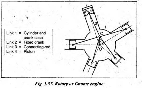
2. Rotary Engine (or
Gnome) Engine
• Rotary engine, also known
as Gnome engine, is a multi-cylinder rotary internal combustion engine. It is
also known as V-type engine.
• This type of rotary
engine was used in the past as an aero-engine, but now it has been replaced by
gas turbines.
• In a rotary engine, as shown in Fig.
1.37, the slider is replaced by a piston and link 1 by a cylinder pivoted at O.
Moreover, instead of one cylinder, odd number of cylinders (e.g., five or seven
cylinders) symmetrically placed at regular intervals in the same plane.
• The link 2 (i.e., crank
OC) is fixed and is common to all cylinders.
• When the fuel burns
inside the cylinders, the pistons reciprocate in the cylinders and at the same
time the whole assembly of bylinders, pistons and connecting rods rotate about
O. The entire mechanical power developed can be obtained in the form of rotation
of crank shaft.
• Thus from Fig. 1.37, it
will be seen that each piston, connecting rod and cylinder form with the fixed
crank OC an inversion of the slider-crank chain.
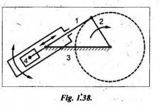
3. Third Inversion
• Third inversion is
obtained by fixing the link 3 of the slider-crank mechanism, as shown in Fig.
1.38. In this, link 2 again acts as a crank and link 4 oscillates.
• Applications:
1. Oscillating cylinder engine, and
2.
Crank and slotted lever mechanism.
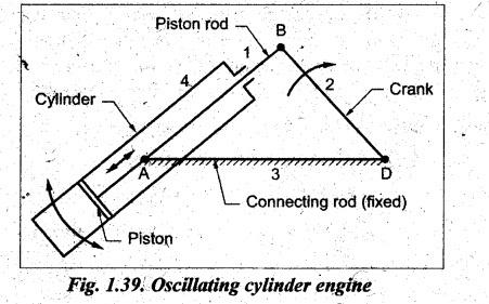
1. Oscillating
Cylinder Engine
• The oscillating cylinder
engine mechanism is used to convert reciprocating motion into rotary motion,
as shown in Fig.1.39.
• In this mechanism, link 3 is
fixed. When the link 2 (crank) rotates, the piston attached to
link
1 (piston rod) reciprocates and the link 4 (cylinder) oscillates about a pin
pivoted to the fixed link A.
2. Crank and Slotted
Lever Quick-Return Motion Mechanism
• The crank and slotted
lever quick-return motion mechanism is mostly used in shaping and slotting
machines. This mechanism is also obtained by fixing
the link 3, as shown in Fig.1.40.
• In this mechanism, link 1
is a slider which slides in a slotted lever (link 4); link 3 is fixed and link
2 is crank which rotates in clockwise direction about point A in a circle and
as a result, the link 4 oscillates about the point O. The link 5 transmits the
motion from link OC to ram which carries the tool.
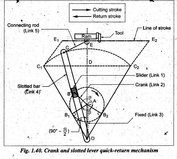
• As shown in Fig.1.40, the
extreme positions OC1 and OC2 are tangential to the
circle. The cutting stroke and return stroke occurs when crank moves from E1
to E2 and E2 to E1 respectively. This will occur
when crank AB moves from B1 to B2 through α angle for
cutting stroke and from B2 to B1 through β angle for
return stroke.
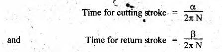
• Since driving crank rotates at
uniform angular speed, we can write
Time
for cutting stroke = α/2π
N
and
Time for return stroke = β /2π N
• The ratio of cutting
stroke to return stroke time (Q) will be given by
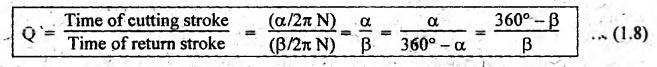
Since
β is less than α, the time required for return stroke is less than cutting
stroke. Thus this mechanism is also called quick-return mechanism.
Note
In
crank and slotted level quick-return mechanism, the travel of the tool or
length of stroke 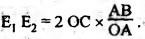
4. Fourth Inversion
• Fourth inversion is
obtained by fixing the link 4 of the slider-crank mechanism, as shown in
Fig.1.41.
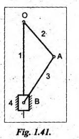
• In this inversion, link 3
can oscillate about the fixed pivot B on link 4. This makes end A of link 2 to
oscillate about B and end O to reciprocate along the axis of the fixed link 4.
• Applications:
1.
Pendulum pump (or Bull engine), and
2.
Hand pump.
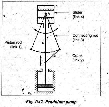
1. Pendulum Pump (or
Bull Engine)
• This mechanism is used to
supply feed water to boilers.
• This mechanism is
obtained by fixing the link 4 (i.e., cylinder), as shown in Fig.1.42. In this
case, when tink 2 (crank) rotates, link 3 (connecting rod) oscillates like a
pendulum about a pin pivoted to the fixed link 4 at A and link 1 reciprocates.
This reciprocating motion of link 1 can be used for a pump.
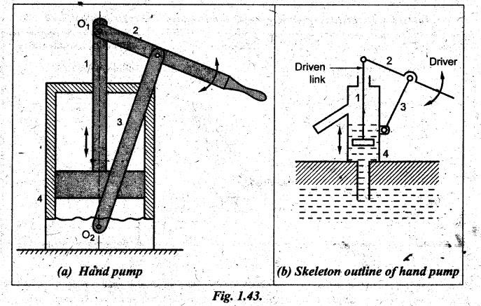
2. Hand Pump
• Hand pump mechanism is
also obtained by fixing the link 4.
• Figs. 1.43(a) and (b)
show the hand pump mechanism in which link 1 reciprocates vertically in fixed
link 4, at the same time link 2 and link 3 will oscillate about the pin joint O1
and O2 respectively.
Theory of Machines: Unit I: Kinematics of Mechanisms : Tag: : Kinematics of Mechanisms - Theory of Machines - inversions of single slider-crank chain
Related Topics
Related Subjects

Theory of Machines
ME3491 4th semester Mechanical Dept | 2021 Regulation | 4th Semester Mechanical Dept 2021 Regulation