Theory of Machines: Unit I: Kinematics of Mechanisms
inversions of four-bar chain
Kinematics of Mechanisms - Theory of Machines
From a four-bar chain, four different inversions can be obtained by fixing its four links one at a time in turn.
INVERSIONS OF FOUR-BAR CHAIN
• From a four-bar chain,
four different inversions can be obtained by fixing its four links one at a
time in turn. Applying each of the inversions, several useful mechanisms can be
obtaind.
• Table 1.4 shows the inversions of
four-bar mechanism and their important applications.
Table 1.4. Inversions of four-bar chain

1. First/Second Inversion (Crank-Rocker Mechanism)
• As shown in Fig.1.27(a),
link 1 is the crank, link 4 is fixed and link 3 oscillates whereas in
Fig.1.27(b), link 2 is fixed and link 3 oscillates. The mechanism thus obtained
is known as crank-rocker mechanism or crank-lever mechanism or
rotary-oscillating converter.

• Application:
Beam engine
Beam Engine
• Beam engine is an example
of crank-rocker mechanism, where one link oscillates, while the other rotates
about the fixed link, as shown in Fig.1.28.
• When the crank (link 1)
rotates, the lever (link 3) oscillates. The oscillatory motion of the lever is
converted into reciprocating motion of a plunger in a cylinder as shown in Fig.
1.28.
• Thus this mechanism is
used to convert the rotary motion into reciprocating motion.

2. Third Inversion (Double-Crank Mechanism)
• If the shortest link,
i.e., link 1 (crank) is fixed, the adjacent links 2 and 4 would make complete
revolutions, as shown in Fig.1.29. The mechanism thus obtained is known as crank-crank
mechanism or double-crank mechanism or rotary-rotary converter drag link
mechanism.

• Application:
Coupling of the locomotive wheels.
1. Coupling of
Locomotive Wheels
• Coupled wheels of a
locomotive is an example of a double-crank mechanism where both cranks rotate
about the points in the fixed link. It consists of four links and the opposite
links are equal in length, as shown in Fig.1.30.
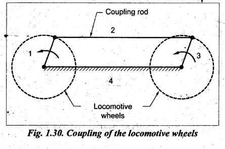
• Since links 1 and 3 work as two
cranks, the mechanism is also known as rotary-rotary converter.
• This mechanism is used to
transmit rotary motion from one wheel to the other' wheel.
3. Fourth Inversion (Double-Rocker Mechanism)
• If the link opposite to
shortest link is fixed, i.e., link 3 is fixed, then the shortest link (link 1)
is made coupler and the other two links 2 and 4 would oscillate as shown in
Fig.1.31. The mechanism thus obtained is known as rocker-rocker or or
double-lever double-rocke mechanism or oscillating-oscillating converter.

• Applications:
1. Watt's indicator mechanism
2.
Pantograph
3.
Ackermann steering
1. Watt's Indicator
Mechanism
• This mechanism was
invented by James Watt for his steam engine to guide the piston rod along
straight line. It is also known as simplex indicator.
• As shown in Fig.1.32, the
Watt's indicator mechanism consists of four links: Link 3 is fixed, link 2 is
ABC, link 3 is CDP, and link 1 is BED.

• Links ABC and CDP act as
levers and due to this, the mechanism is also known as double-lever or double-rocker
mechanism.
• The point E is connected
to piston of indicator cylinder and the displacement of point E (and link BED)
is directly proportional to the steam or gas pressure in the indicator diagram.
• In Fig.1.32, continuous lines depict
the initial position of the mechanism, whereas the dotted lines show the
position of the mechanism when steam or gas pressure acts on the indicator
piston.
• The point P (of the link
CDP) traces the variation of pressure in the cylinder. It may be noted that the
point P traces approximately the straight line motion (PP') corresponding to
motion of E. For this reason, this mechanism is also known as straight
line generator mechanism.
2. Pantograph
Pantograph
is a device which is used to reproduce a displacement exactly in an enlarged or
reduced scale.
3. Ackermann Steering
The
Ackermann steering mechanism is used for changing the direction of the wheel
axles with reference to the chasis, so as to move the vehicle in any desired
path.
Theory of Machines: Unit I: Kinematics of Mechanisms : Tag: : Kinematics of Mechanisms - Theory of Machines - inversions of four-bar chain
Related Topics
Related Subjects

Theory of Machines
ME3491 4th semester Mechanical Dept | 2021 Regulation | 4th Semester Mechanical Dept 2021 Regulation