Theory of Machines: Unit I: Kinematics of Mechanisms
inversions of double slider-crank chain
Kinematics of Mechanisms - Theory of Machines
The double slider-crank chain provides three different inversions.
INVERSIONS OF DOUBLE SLIDER-CRANK CHAIN
The
double slider-crank chain provides three different inversions. Table 1.6 shows
the inversions of double slider-crank chain and their important applications.
Table 1.6. Inversions of double slider-crank chain and their
applications
• By fixing any of the
two sliders in the double slider-crank chain only scotch yoke mechanism is
obtained. Therefore, only three different mechanisms/inversions are obtained
from double slider-crank chain.
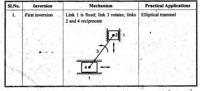
1. First Inversion
• First inversion is
obtained by fixing the link 1.
• In this, the two adjacent
pairs 2-3 and 3-4 are turning pairs and the other two pairs 1-2 and 1-4 are
sliding pairs.
• Application:
Elliptical trammel
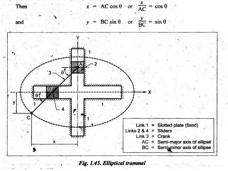
1. Elliptical Trammel
• Elliptical trammel is an
instrument used for drawing ellipses.
• This inversion is
obtained by fixing the link 1 (i.e., slotted plate), as shown in Fig.1.45. The
link 1 or the fixed plate has two straight grooves in it, at right angles to
each other.
• When the links 2 and 4
(sliders) slide along their respective grooves, the end C of the extension BC
of the link AB, traces an ellipse such that AC and BC are the semi-major and
semi-minor axis of the ellipse respectively.
• Proof:
Let AC makes an angle θ as shown in Fig.1.45 and co-ordinates of
point C be (x, y).
Squaring
and adding, we get

which
is the equation of an ellipse.
The
above expression proves that AC is the semi-major axis of the ellipse and BC is
the semi-minor axis of the ellipse.
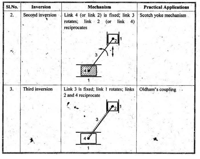
2. Second Inversion
• Second inversion is
obtained by fixing any one of the slider blocks (i.e., link 2 or link 4) of the
first inversion.
• When link 4 is fixed, end
B of crank 3 rotates about A and link 1 reciprocates in the horizontal
direction.
• Application:
Scotch yoke mechanism
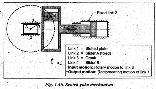
1. Scotch Yoke
Mechanism
• This inversion is used
for converting rotary motion into reciprocating morton. Nowadays,
it is used as sine-cosine generator for computing elements and as a mechanism on
a test machine to produce vibrations.
• It is obtained by fixing
any one of the sliders (here link 2), as shown in Fig.1.46. As crank 3 rotates
about fixed point A, the horizontal portion of link 1 slides or reciprocates in
the fixed link 2. The slider B (which is attached to crank) reciprocates. This
causes the slotted lever frame (link 1) to reciprocate. The fixed slider A
guides the frame to reciprocate. Thus this mechanism converts rotary motion of
link 3 into reciprocating motion of link 1.
3. Third inversion
• Third inversion is
obtained by fixing the link 3 as shown in Table 1.6.
• When link 3 iş fixed,
link I rotates and links 2 and 4 reciprocate.
• Application:
Oldham's coupling.
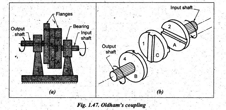
1. Oldham's Coupling
• The Oldham's coupling is used
for transmitting motion between two shafts when (i) the shafts are parallel,
but not coaxial, and (ii) the centre distance between their centre lines is
small.
• The shafts are coupled in
such a way that if one shaft rotates, the other shaft also rotates at the same
speed.
• The inversion is obtained
by fixed the link 3 as shown in Fig.1.47.
• It consists of a driving
shaft, fitted with a flange (link 2) having a diametrical slot on its face; a
driven shaft fitted with flange C (link 4) also has diametrical slot on its
face. This whole makes link 4. The slots on the two flanges are at right angles
to each other. An intermediate piece circular shape, having tongues X and Y at
right angles on opposite sides, is fitted in between the flanges of the two shafts
in such a way that the tongues of the intermediate piece get fitted closely in
the slots of flanges. The intermediate circular piece E forms link 1 which
slides between the flanges C and D.
• When driving shaft
rotates through certain angle, the driven shaft also rotates through the same
angle. Motion is transmitted through intermediate link 1. If the distance
between the axis of the shafts is x, it will be the diameter of a circle traced
by the center of intermediate piece.
• The maximum sliding
velocity of each tongue along its slot is given by
vs
= r . ω
where
vs
= maximum sliding velocity of each tongue along its slot,
r
= Distance between the axis of shafts, and
ω
= Angular velocity of the shaft.
Theory of Machines: Unit I: Kinematics of Mechanisms : Tag: : Kinematics of Mechanisms - Theory of Machines - inversions of double slider-crank chain
Related Topics
Related Subjects

Theory of Machines
ME3491 4th semester Mechanical Dept | 2021 Regulation | 4th Semester Mechanical Dept 2021 Regulation