Theory of Machines: Unit IV: Force Analysis
inertia force analysis in a reciprocating engine, considering the weight of connecting rod
Force Analysis - Theory of Machines
The inertia force analysis in reciprocating engines becomes necessary due to their higher operating speed.
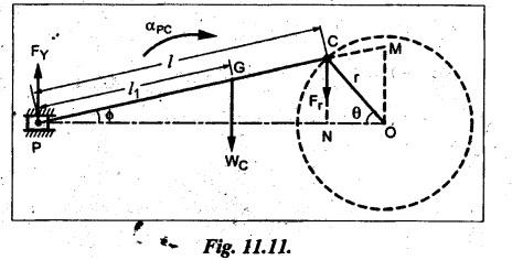
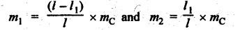
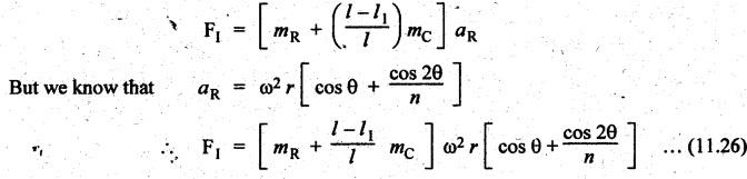
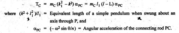
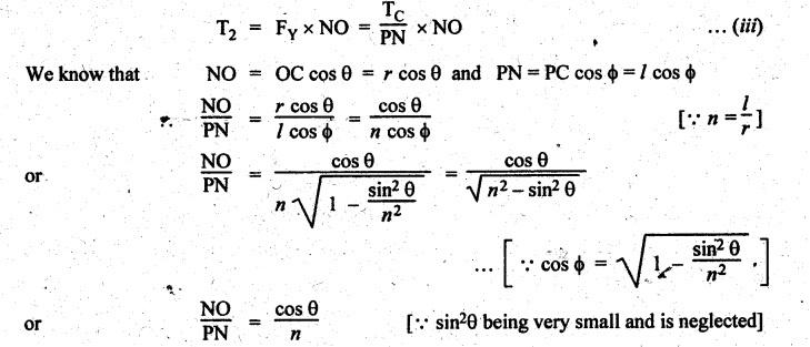
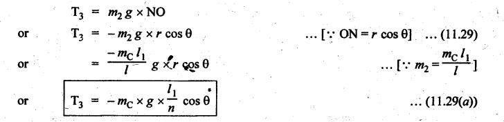
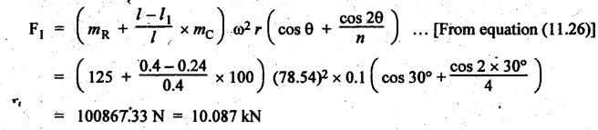
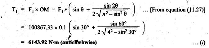
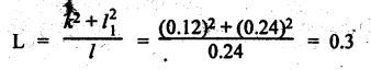
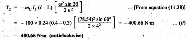
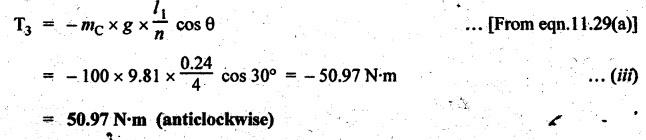
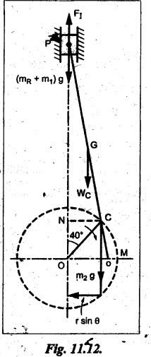
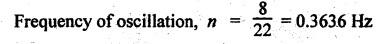
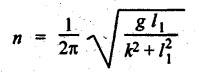
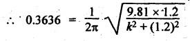
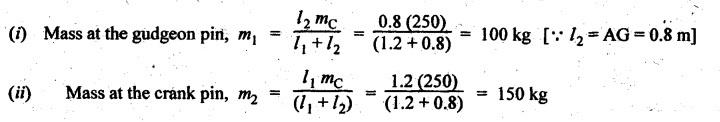
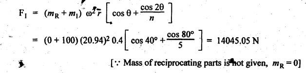
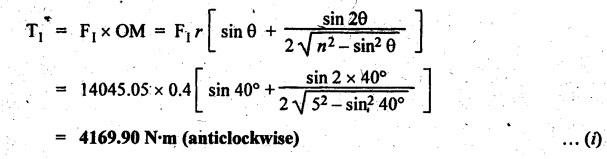
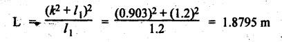
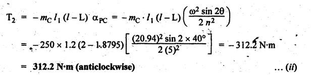
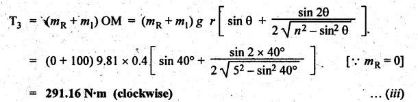
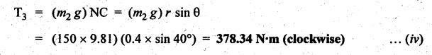
INERTIA FORCE ANALYSIS IN A RECIPROCATING ENGINE, CONSIDERING THE WEIGHT OF CONNECTING ROD The inertia force analysis in reciprocating engines becomes necessary due to their higher operating speed. In a reciprocating engine, let OC be the crank and PC the connecting rod whose center of gravity lies at G. The inertia forces in a reciprocating engine can be determined graphically as well as analytically. A reciprocating engine mechanism is shown in Fig.11.11. The inertia force of the crankshaft and its effect on the crankshaft torque is determined analytically as follows: Step 1: Let two masses m1 and m2 be placed at P and C such that sum of both are equal to mC (ie., mass of the connecting rod) and their center of gravity coincides with G. Step 2: The inertia force due to the mass at C acts radially outwards along the crank OC, therefor the mass at C has no effect on the crankshaft torque. Step 3: To determine m1 and m2 Let m1 = Mass placed at small end centre P, m2 = Mass placed at big end centre C, mC = Mass of the connecting rod, l = Length of the connecting rod, and l1 = Length of the center of gravity fo the connecting rod from P. We know that for dynamically equivalent system, From equations (i) and (ii), we get Step 4: To determine torque exerted on the crankshaft due to inertia force (T1): Now at P, two forces acts first the weight of the reciprocating parts WR (i.e., MR • g) and the other W1 (i.e., m1•g). Then, total inertia force of the equivalent mass acting at P, and corresponding torque exerted on the crankshaft, Step 5: To determine torque exerted on crankshaft due to correction couple (T2): Placing of weights at P and C does not satisfy the condition of dynamical equivalent system as such correcting torque is necessary to undo the error. The correcting couple TC is introduced by two equal parallel and opposite forces FY acting through P and C. and corresponding torque on the crankshaft, Substituting this value in equation (iii), we get Step 6: To determine torque exerted on crankshaft due to mass m2 placed at big end centre C (T3): Torque exerted on the crankshaft due to the mass m2 placed at C is given by Step 7: To determine resultant inertia torque exerted on crankshaft (T): The total torque exerted on the crankshaft due to the inertia of the moving parts is the algebraic sum of T1, T2 and T3. Note If crank is rotating in clockwise direction, then T1 and T2 will act in the anticlockwise direction, and vice versa. The direction of T3 depends on the crank angle θ. Example 11.19 The connecting rod of a horizontal reciprocating engine is 400 mm and length of the stroke is 200 mm. The mass of the reciprocating parts is 125 kg and that of the connecting rod is 100 kg. The radius of gyration of the connecting rod about an axis through the centre of gravity is 120 mm and the distance of centre of gravity of the connecting rod from big end centre is 160 mm. The engine runs at 750 rpm. Determine the torque exerted on the crankshaft when the crank has turned 30° from the inner dead centre. Given data: l = PC = 400 mm 0.4 m; L = 200 mm = 0.2 m or r = L/2 = 0.2/2 = 0.1 m; mR = 125 kg; mC = 100 kg; k = 120 mm = 0.12 m; GC = 160 mm = 0.16 m; N = 750 rpm; θ = 30°. Solution: ω = 2πN/60 = 2л (750)/60 = 78.54 rad/s Analytical Method To find T1: We know that the distance of centre of gravity (G) of the connecting rod from P, l1 = l – GC = 0.4 - 0.16. = 0.24 m Inertia force due to total mass of the reciprocating parts at P, ⸫ Corresponding torque exerted on crankshaft due to inertia force F1 is given by, To find T2: We know that equivalent length of a simple pendulum which swung about an axis through P, The torque due to correction couple (TC) is given by To find T3: Torque exerted due to the weight of the connecting rod at C is given by To find T: We know that the total inertia torque exerted on the crankshaft, is the algebraic sum of T1, T2 and T3. Note It may be noted that there is a difference in the values of total inertia torque (T) determined by graphical and analytical method. It is due to practical error in constructing the Klien's construction and due to the fact that the analytical equations are only approximate. Example 11.20 The connecting rod of a vertical reciprocating engine is 2 m long between centers and its mass is 250 kg. The mass center is 800 mm from the big end bearing. When suspended as a pendulum from the gudgeon pin axis, it makes 8 complete oscillations in 22 seconds. The crank is 400 mm long and rotates at 200 rpm. Determine by analytical method: (i) the radius of gyration of the connecting rod about an axis through its mass center; and (ii) the inertia torque exerted on the crankshaft, when the crank has turned through 40o from TDC and the piston is moving downwards. Given data: l = PC = 2 m; mC = 250 kg; GC = 800 mm = 0.8 m; r = 400 mm = 0.4 m; N = 200 rpm; θ = 40°. Solution: ω = 2πN/60 = 2π(200)/60 = 20.94 rad/s The configuration of the vertical reciprocating engine is shown in Fig.11.12. (i) Radius of gyration of the connecting rod about its C.G(k): The connecting rod acts as a compound pendulum. Since the connecting rod makes 8 complete oscillations in 22 seconds, therefore We know that for a compound pendulum, frequency of oscillations is given by where l1 = Distance of C.G from the point of suspension = PG = 2 - 0.8 = 1.2 m On solving, we get Radius of gyration, k = 0.903 m Ans. 2. Inertia torque exerted on the crankshaft (T): First of all, let us divide the mass of the connecting rod (mC) into two parts. Inertia force due to reciprocating parts is given by ⸫ Corresponding torque exerted on crankshaft due to inertia force is given by We know that the equivalent length of a simple pendulum when swung about an axis passing through P, The torque due to correction couple (TC) is given by Torque due to weight of the reciprocating parts (both mŔ and mass m1 at P) is given by Torque exerted on crankshaft due to mass m2 at big end bearing C is given by ⸫ Total inertia torque exerted on the crankshaft, T = T1 + T2 + T3 + T4 = -4169.09 – 312.2 + 291.16 + 378.34 = −3811.78 N•m = 3811.78 Nm (anticlockwise) Ans. 1. Analytical Method


Theory of Machines: Unit IV: Force Analysis : Tag: : Force Analysis - Theory of Machines - inertia force analysis in a reciprocating engine, considering the weight of connecting rod
Related Topics
Related Subjects

Theory of Machines
ME3491 4th semester Mechanical Dept | 2021 Regulation | 4th Semester Mechanical Dept 2021 Regulation