Manufacturing Technology: Unit III: Reciprocating Machine Tools
Indexing or dividing heads
Reciprocating Machine Tools - Manufacturing Technology
Indexing is the process of dividing the periphery of a job into equal number of divisions.
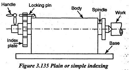
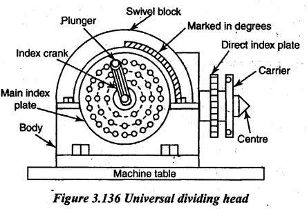
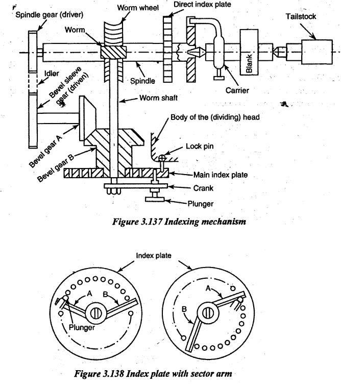
INDEXING OR DIVIDING HEADS Indexing is the process of dividing the periphery of a job into equal number of divisions. For doing this indexing, an attachment known as dividing head is used in the milling machine. These dividing heads are of following three types. 1. Plain or simple dividing head 2. Universal dividing head 3. Optical dividing head. Figure 3.135 illustrates the process of simple indexing. This type of dividing head is hand-operated and it is used for simple indexing. It is the simplest of all dividing heads. It has a cylindrical spindle. The hand wheel directly rotates the spindle. An index plate is connected to the left end of the spindle. The index plate is a circular plate having 24 or 12 slots which are equally spaced on the periphery. A handle is connected to the tail end of the spindle. The spindle may be rotated through a desired angle and clamped by inserting the clamping lever into any one of the equally spaced holes or slots. By means of this dividing head, 2, 3, 4, 6, 18, 12 and 24 divisions can be obtained when a 24 slot plate is used and 2, 3, 4, 6 and 12 divisions can be obtained when a 12 slot plate is used. The job is held between two centres. One is on the dividing head spindle and other is on the tailstock. The hand lever is used for locking the spindle in position. In this dividing head, there is no worm and worm wheel. This dividing head is a very much useful device for the purpose of indexing work. Figure 3.136 shows the outside view of the universal dividing head. The worm drive is enclosed in a strong body. The base of the body has two slots which are used for mounting the dividing head with the milling machine. The driving mechanism consists of a worm drive, index plates, sector arms, change gears and spindle as shown in Figure 3.137. The main spindle is housed on two accurate bearings. A worm gear (worm wheel) is keyed to the spindle. The worm meshes with the worm gear. The worm is mounted on a worm shaft. The crank is fitted at the other end of the worm shaft. The worm gear has 40 teeth and the worm is single threaded. So, 40 turns of the crank will move the spindle by one complete revolution. It means, every rotation of main index crank turns the worm or spindle through 1/40 of a revolution. Fractional parts of a turn are obtained by utilizing index plates. An index plate is a circular disc having equally spaced holes arranged in concentric circles as shown in Figure 3.136. The index plate is fastened to a bevel gear B which is loosely mounted on a worm shaft. Normally, the index plate is kept stationary by a lock pin. The lock pin locks the index plate with the body of the dividing head. A spring loaded pin of the crank fits into holes in the index plate. If the pin is moved from one hole to the next in a 24-hole circle of the index plate, the spindle will revolve by 1/40 x 1/24 1/960 of a turn. The sector arms A and B as shown in Figure 3.138 are used for the movement of the pin without counting the holes each time of the crank movement. The live centre is fitted into a dividing head spindle which has a taper hole to receive it. The nose has got threads to hold a chuck or driving plate. The work is held between two centres. A swiveling arrangement is provided for the spindle. The spindle can be tilted through any angle, 5° below horizontal to 10° beyond vertical. The spindle can be clamped in an inclined position. The dividing head spindle can be connected to the table feed screw. through gear train for helical milling. Thus, a continuous rotary motion of the workpiece is obtained. Uses: The universal dividing head is used for the following purposes: 1. It is used to set the workpiece in a desired position (i.e. vertical, horizontal or in inclined position) in relation to the machine table. 2. To rotate the job through a desired angle to cut teeth. 3. It provides a continuous rotary motion to the job during milling of helical gears. 4. It is used to hold the workpiece and support it in conjunction with a tailstock.1. Plain or Simple Dividing Head
2. Universal Dividing Head
Manufacturing Technology: Unit III: Reciprocating Machine Tools : Tag: : Reciprocating Machine Tools - Manufacturing Technology - Indexing or dividing heads
Related Topics
Related Subjects

Manufacturing Technology
ME3493 4th semester Mechanical Dept | 2021 Regulation | 4th Semester Mechanical Dept 2021 Regulation