Hydraulics and Pneumatics: Unit I: Fluid Power Priniciples and Hydraulic Pumps
Hydraulic power system (layout of a hydraulic system)
Fluid Power Priniciples and Hydraulic Pumps - Hydraulics and Pneumatics
As we know, the hydraulic system uses the pressurized hydraulic liquid as the fluid medium. Also hydraulic system is always a closed loop system.
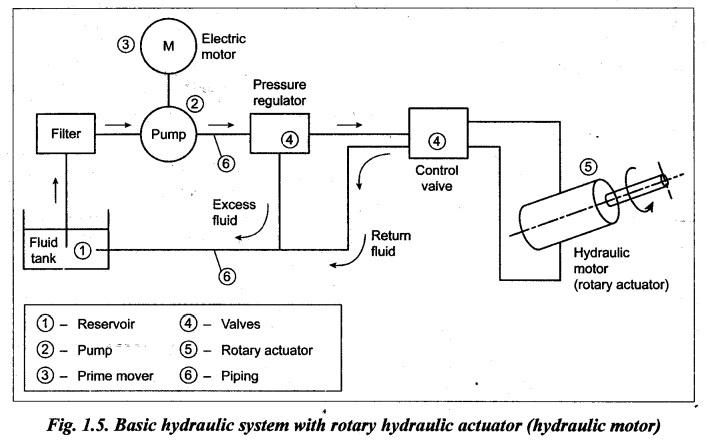
HYDRAULIC POWER SYSTEM (LAYOUT OF A HYDRAULIC SYSTEM) As we know, the hydraulic system uses the pressurized hydraulic liquid as the fluid medium. Also hydraulic system is always a closed loop system. 1. Arrangement The general arrangement of a basic hydraulic system is shown in Fig.1.4. 2. Basic Components of a Hydraulic System • A hydraulic system consists of six basic components, as shown in Fig. 1.4(b). The basic components and their functions are presented in Table 1.6. Table 1.6. Basic components of a hydraulic system 1. Reservoir (or tank): A reservoir is an oil supply tank. It is provided to hold the hydraulic liquid (usually oil). 2. Pump: A pump is used to force the liquid into the system. 3. Prime mover: A prime mover, usually an electric motor, is used to drive the pump. 4. Valves: Valves are fitted in the system to control liquid direction, pressure, and flow rate. 5. Actuator: An actuator is provided to convert the liquid energy into mechanical force or torque to do useful work. The actuator is the actual. working element of the system. The actuators can be either cylinders (to provide linear motion) or hydro motors (to provide rotary motion). 6. Fluid-transfer piping: The hydraulic piping is provided to carry the liquid from one place to another. • It may be noted that many different circuit designs are possible for a given application. However, most industrial hydraulic circuits represent some variation in the design of basic components. • The output of the hydraulic system can be determined by the manner in which the various components are arranged. 3. Working 1. How does a Hydraulic Cylinder (Actuator) Work? The schematic arrangement of the hydraulic cylinder is shown in Fig.1.4(a). It consists of a movable piston connected to the output shaft and two parts A and B. If liquid is pumped through port A, then the piston will move up; and if the liquid is pumped through port B, then the piston will move down. Obviously, when the pressurized liquid is pumped at one side of the piston, then the non-pressurized liquid on the other side of the piston must be retrieved back to the liquid tank. 2. Working of the Total Hydraulic System 'The total hydraulic system for the task of moving a weight (W) by a distance (D) is shown in Fig.1.4(b). The parts enclosed in the dotted-lined box are common to an area of the plant, which may have many linear and rotary hydraulic actuators. In this case, we use only one linear hydraulic actuator. These hydraulic components are studied in detail in subsequent chapters; pumps are discussed in Chapter 4; motors and actuators in Chapter 5; and valves in Chapter 6; and so on. AC induction motor (M) drives the hydraulic pump (P), so that the fluid is pumped from the tank at the required pressure. The fluid circulated into the system should be clean to reduce the wear of the pump and cylinder; hence a filter is used immediate to the storage tank. Since the pump delivers constant volume of fluid for each revolution of the shaft, the fluid pressure rises indefinitely, until a pipe or pump itself fails. To avoid this, some kind of pressure regulator is used to spill out the excess fluid back to the tank. Cylinder movement is controlled by a 3-position changeover control valve. One side of the valve is connected to a pressurized fluid line and the fluid retrieval line; and other side of the valve is connected to port A and port B of the cylinder. Since the hydraulic circuit is a closed one, the liquid transferred from the storage tank to one side of the piston, and the fluid at the other side of the piston is retrieved back to the tank. 3. Positions of Valve Raise: To lift the weight, the pressurized fluid line has to be connected to port A and the retrieval line has to be connected to the port B, by moving the valve position to ‘raise’. Lower: To bring down the weight, the pressurized fluid line has to be connected to port B and the retrieval fluid line has to be connected to port A, by moving the valve position to 'lower'. Off: The weight can be stopped at a particular position (height) by moving the valve position to 'off'. This disconnects the port A and port B from the pressurized line and the retrieval line, which locks the fluid in the cylinder. Note Other key points to be noted in the above hydraulic system are : • Speed of the cylinder movement can be regulated through the volume flow rate to the cylinder. Precision is very good at low speed. • Travel limits are determined by the cylinder stroke. • AC induction motor requires a motor starter and overload protection. 4. An Alternative Hydraulic System It may be noted that the hydraulic system illustrated in Fig.1.4 uses linear hydraulic actuator (i.e., hydraulic cylinder), which provides linear motion (i.e., up and down movement) of the piston. An alternative hydraulic system to that in Fig.1.4 is illustrated in Fig.1.5. In this alternative hydraulic system, the linear hydraulic actuator (cylinder) is replaced by a rotary actuator (hydraulic motor). The working of this hydraulic system is exactly the same as that of the system illustrated in Fig.1.5, except that the output motion is rotary motion instead of linear motion. Note • The hydraulic system with linear actuator (Fig.1.4) find applications in various areas. Typical examples are the braking systems used in cars, and the steering gear of aircraft whereby the direction of the rudder and hence the aircraft is controlled. • Typical examples using the hydraulic system with rotary actuator (Fig.1.5) are a hydraulic winch drive and the hydrostatic drive on a vehicle. 5. Advantages of Hydraulic Power Systems Table 1.4 lists the general advantages which are applicable to both hydraulic and pneumatic power systems. However the specific advantages of using hydraulic power systems are presented in Table 1.7. Table 1.7. Advantages of hydraulic power systems 1. Hydraulic power is easy to generate, transmit, store, regulate and control, maintain and transform. 2. Hydraulic power systems can generate and transmit large tonnes and forces to any part of a machine. It is also possible to amplify (i.e., multiply) the force and power. 3. The hydraulic power systems provide reversible, infinitely variable speed and load control. 4. They can achieve accurate feed back control of load, position, etc. 5. They offer cushioning for shock loads. Hence the noise and vibration produced are minimal. 6. The wear of the system is reduced due to the self-lubrication action of the transmission medium. 7. They are mechanically safe, compact and can be easily controlled. 8. The power-to-weight ratio of a hydraulic power system is comparatively higher than that for electrical and mechanical power systems. 9. The hydraulic output can be linear and rotational. Use of flexible connection hydraulic system permits generation of complex motion, which is impractical with the kinematic linkages such as gear, belts, cams, etc. 10. The hydraulic power systems offer safe operation for both operator and machine. 11. Hydraulic elements can be located easily at any place and can be controlled reversely. 12. This system is a better over-load safe power system. This can be easily achieved by using a pressure relief valve. 6. Disadvantages of Hydraulic Power Systems Table 1.8 presents some of the major disadvantages of hydraulic systems. Table 1.8. Drawbacks of hydraulic power systems 1. Hydraulic fluid leakage poses many problems to the operations as well as operators. 2. Flammable hydraulic fluids may pose fire hazards thus limiting the upper level of working temperature. 3. Hydraulic elements require special treatments to protect them against rust, corrosion, dirt, etc. Otherwise the contaminated elements may impair the system operation. 4. Hydraulic fluids may pose problems if it disintegrates due to ageing and chemical deterioration.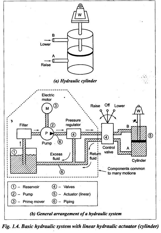
Hydraulics and Pneumatics: Unit I: Fluid Power Priniciples and Hydraulic Pumps : Tag: : Fluid Power Priniciples and Hydraulic Pumps - Hydraulics and Pneumatics - Hydraulic power system (layout of a hydraulic system)
Related Topics
Related Subjects

Hydraulics and Pneumatics
ME3492 4th semester Mechanical Dept | 2021 Regulation | 4th Semester Mechanical Dept 2021 Regulation