Hydraulics and Pneumatics: Unit III: Hydraulic Circuits and Systems
hydraulic cylinder synchronizing circuits
Hydraulic Circuits and Systems - Hydraulics and Pneumatics
Synchronizing circuits are used where the motion of two or more cylinders is required to be operated simultaneously, irrespective of load on individual cylinder.
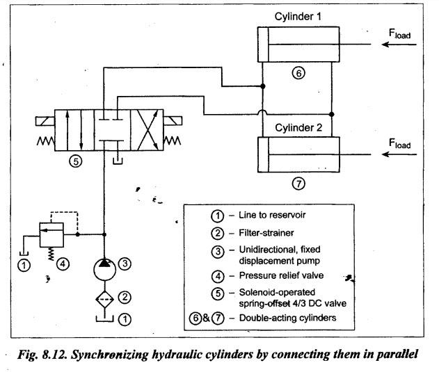
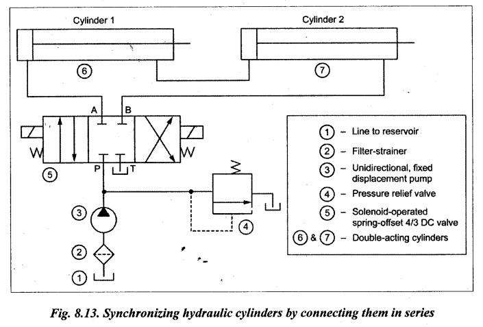
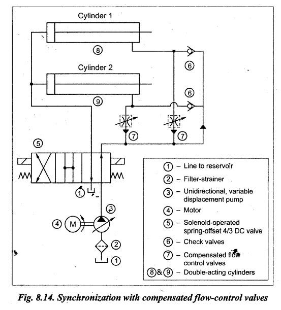
HYDRAULIC CYLINDER SYNCHRONIZING CIRCUITS • Synchronizing circuits are used where the motion of two or more cylinders is required to be operated simultaneously, irrespective of load on individual cylinder. • There are many industrial applications require nearly perfect synchronization of movement of two or more cylinders in order to complete some phase of operation. To accomplish the identical task from the cylinders at the same rate, synchronizing circuits are employed. • This synchronization can be achieved: (i) by using two cylinders in parallel, and (ii) by using two cylinders in series. 1. Circuit Fig.8.12 illustrates a circuit to synchronize two cylinders by connecting them in parallel. This circuit uses a solenoid-operated, spring offset 4/3 DC valve and two double-acting hydraulic cylinders. 2. Operation It may be noted that the following two conditions are to be satisfied for the perfect synchronization of two cylinders: (i) Size of both the cylinders should be identical; and (ii) Load on both the cylinders should be of same magnitude. When the loads are not of same magnitude, the cylinder with smaller load extends first. Thus the two cylinders are not synchronized. Practically, no two cylinders are identical, because of packing (i.e., seals) friction differences. Thus two cylinders hooked in parallel will not operate in perfect synchronization. For perfect synchronization of two cylinders, they have to be connected in series. 1. Circuit Fig.8.13 illustrates a circuit to synchronize two cylinders by connecting them in series. This circuit uses a solenoid-operated, spring-offset 4/3 DC valve and two double-acting hydraulic cylinders. 2. Operation Extension of cylinders 1 and 2: When the 4/3 DC valve is shifted to the left envelope flow path configuration, oil flows from the pump to the blind end of cylinder 1 and thus the cylinder 1 extends. At the same time, oil from the rod end of cylinder 1 is forced to the blind end of cylinder 2 and thus the cylinder 2 also extends. Now the oil returns to the tank from the rod end of cylinder 2 via the DC valve. Once full extension of cylinders 1 and 2 are over, the DC valve is shifted to the right mode. Retraction of cylinders 1 and 2: When the 4/3 DC valve is shifted to the right mode, oil flows from the pump to the rod end of cylinder 2 and thus the cylinder 2 retracts. At the same time, oil from the blind end of cylinder 2 is forced to the rod end of cylinder 1 and thus the cylinder 1 also retracts. Now the oil returns to the tank from the blind end of cylinder 1 via the DC valve. Thus both extension and retraction operations of both cylinders are synchronized by connecting them in series. But for the two cylinders to be synchronized, the piston area of cylinder 2 should be equal to the difference between the areas of the piston and rod for cylinder 1. 1. Circuit Fig. 8.14 illustrates a circuit to synchronize two hydraulic cylinders using two flow control valves. 2. Operation In this synchronizing circuit, the two flow control valves can be set independently and equal volumes of fluid to or from each cylinder can be obtained; and this results in simultaneous movement of the two cylinders.1. Synchronizing Hydraulic Cylinders Connected in Parallel Circuit
2. Synchronizing Hydraulic Cylinders Connected in Series
3. Synchronizing Hydraulic Cylinders with Flow Control Valves
Hydraulics and Pneumatics: Unit III: Hydraulic Circuits and Systems : Tag: : Hydraulic Circuits and Systems - Hydraulics and Pneumatics - hydraulic cylinder synchronizing circuits
Related Topics
Related Subjects

Hydraulics and Pneumatics
ME3492 4th semester Mechanical Dept | 2021 Regulation | 4th Semester Mechanical Dept 2021 Regulation