Hydraulics and Pneumatics: Unit III: Hydraulic Circuits and Systems
hydraulic circuits
Hydraulic Circuits and Systems - Hydraulics and Pneumatics
A hydraulic circuit may be defined as the graphic representation of the hydraulic components in a hydraulically operated machine.
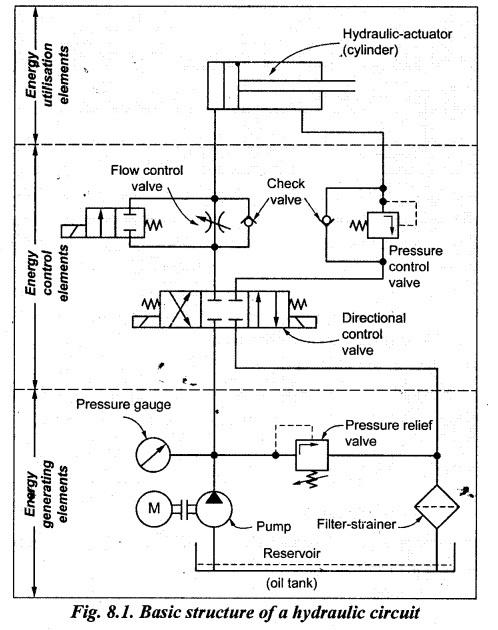
HYDRAULIC CIRCUITS • A hydraulic circuit may be defined as the graphic representation of the hydraulic components in a hydraulically operated machine. • In other words, a hydraulic circuit is an arrangement of interconnected components (such as pumps, actuators, control valves, and pipings), selected to achieve the desired work output. (Essential Components Required for a Hydraulic Circuit Design) • A hydraulic circuit is the symbolic representation of arrangements and connections of various elements of a hydraulic system. • Fig.8.1 illustrates a typical basic structure of a hydraulic circuit. • Since fluid power circuits are developed with the use of components' graphic symbols, therefore the readers should be familiar and thorough with the fluid power symbols before they study fluid power circuits. • As could be seen from Fig.8.1, any hydraulic circuit consists of the following main three groups of components: (i) Energy generating elements: These elements include the oil reservoir, filter- strainer, pump actuating motor, cooler, pressure gauges, temperature switches, etc. (ii) Energy control elements: These elements include pressure control valves, flow control valves and direction control valves, check valves, etc. (iii) Energy utilization elements (or actuators): These elements convert the hydraulic energy into mechanical energy. These elements include cylinders (linear actuators) and motors (rotary actuators). The four important factors should be considered while designing any fluid power (hydraulic/pneumatic) circuit are : 1. Safety of operation, 2. Performance of desired function, 3. Efficiency of operation, and 4. Cost. The design, operation, and purpose of the following hydraulic circuits are presented in this chapter. (i) Control of a single-acting hydraulic cylinder, (ii) Control of a double-acting hydraulic cylinder, (iii) Regenerative circuit, (iv) Regenerative cylinder circuit for machine tool applications, (v) Pump-unloading circuit, (vi) Double-pump hydraulic circuit, (vii) Counterbalance valve application, (viii) Sequencing of two double-acting cylinders, (ix) Automatic cylinder recíprocating system, (x) Synchronizing circuits (a) Synchronizing hydraulic cylinders connected in parallel (b) Synchronizing hydraulic cylinders connected in series (c) Synchronizing hydraulic cylinders with flow control valves (xi) Fail-safe circuits (a) Prevention from inadvertent cylinder extension (b) Overload protection (c) Two-handed safety circuit (xii) Speed control circuits (a) Meter-in circuit (b) Meter-out circuit (c) Bleed-off circuit (xiii) Speed control of a hydraulic motor (xiv) Hydropneumatic circuits1. What is a Hydraulic Circuit ?
2. Basic Structure of a Hydraulic Circuit
3. Factors To Be Considered
4. Important Hydraulic Circuits
Hydraulics and Pneumatics: Unit III: Hydraulic Circuits and Systems : Tag: : Hydraulic Circuits and Systems - Hydraulics and Pneumatics - hydraulic circuits
Related Topics
Related Subjects

Hydraulics and Pneumatics
ME3492 4th semester Mechanical Dept | 2021 Regulation | 4th Semester Mechanical Dept 2021 Regulation