Hydraulics and Pneumatics: Unit V: Trouble Shooting and Applications
Hydraulic circuit for a surface grinding machine
Functional and Operational Requirements, Circuit, Operation
In a surface grinding machine (or a milling machine) the work piece is clamped on the machine table and the machine table is made to reciprocate continuously with same speed during both forward and return strokes.
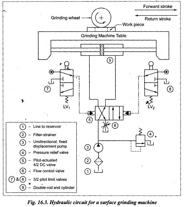
HYDRAULIC CIRCUIT FOR A SURFACE GRINDING MACHINE • In a surface grinding machine (or a milling machine) the work piece is clamped on the machine table and the machine table is made to reciprocate continuously with same speed during both forward and return strokes. The continuous reciprocation of machine table is achieved through automatic reciprocating circuit. • The automatic continuous reciprocation of ram can be obtained either by using solenoid DC valve or by using pilot operated DC valve. Limit switches are to be used if solenoid DC valve is chosen and limit valves are to be used if pilot operated DC valve is chosen. Fig.16.3 illustrates a typical hydraulic circuit used in a surface grinding machine. This circuit uses 4/2 pilot operated DC valves, 2 limit valves (LV1 and LV2), a flow control valve and a double-rod end cylinder. Forward movement of table: When the 4/2 DC valve is shifted to the right envelope flow path configuration, oil flows from the pump into the left end of the cylinder and thus the piston moves from left to right. At the same time, oil at the right side of the cylinder return backs to the reservoir through the DC valve and the flow control valve. When the oil passes through the flow control valve, its flow gets restricted which limits the forward movement of the machine table. At the end of the forward stroke, the pilot limit valve LV1 is actuated by the ram movement. When LV1 is actuated, the pilot flow actuates the DC valve to shift to left envelope mode. Return movement of table: When the 4/2 DC valve is shifted to the right envelope flow path configuration, oil flows from the pump into the right end of the cylinder and thus the piston moves from right to left. At the same time, oil at the left side of the cylinder return backs to the reservoir through the DC valve and the flow control valve. When the oil passes through the flow control valve, its flow gets restricted which limits the return movement of the machine table. At the end of the return stroke, the pilot limit valve LV2 is actuated by the ram movement. When LV2 is actuated, the pilot flow actuates the DC valve to shift to left envelope mode. Thus the cycle of operation is repeated continuously. It may be noted that the flow control valve is placed in a return line to the reservoir in order to obtain same speed of the piston during both strokes.1. Functional and Operational Requirements
2. Circuit
3. Operation
Hydraulics and Pneumatics: Unit V: Trouble Shooting and Applications : Tag: : Functional and Operational Requirements, Circuit, Operation - Hydraulic circuit for a surface grinding machine
Related Topics
Related Subjects

Hydraulics and Pneumatics
ME3492 4th semester Mechanical Dept | 2021 Regulation | 4th Semester Mechanical Dept 2021 Regulation