Hydraulics and Pneumatics: Unit V: Trouble Shooting and Applications
hydraulic circuit for a shaping machine
Trouble Shooting and Applications - Hydraulics and Pneumatics
As we know shaping operation in a shaping machine tool requires slower cutting stroke (forward stroke) and fäster return stroke of the ram.
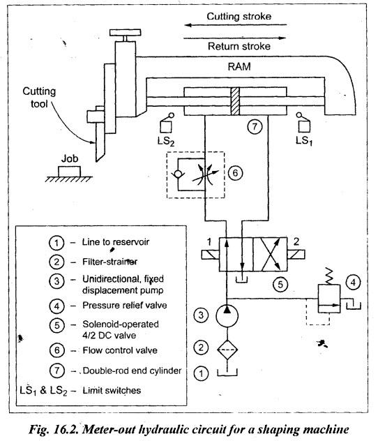
HYDRAULIC CIRCUIT FOR A SHAPING MACHINE (METER-OUT HYDRAULIC CIRCUIT FOR SHAPING OPERATION) As we know shaping operation in a shaping machine tool requires slower cutting stroke (forward stroke) and fäster return stroke of the ram. This can be achieved using a meter-out circuit (or a bleed-off circuit). Also continuous reciprocation of the ram can be achieved by using solenoid operated DC valve and limit switches in the meter-out circuit. Fig.16.2 illustrates a meter-out hydraulic circuit that can be used to produce slower, forward stroke and quick-return stroke of the ram during a shaping operation. This circuit uses 4/2 solenoid operated DC valve, a flow control valve, two limit switches (LS1 and LS2) and a double-rod end cylinder. Forward (cutting) stroke: When the 4/2 DC valve is shifted to the righ nvelope flow path configuration, oil flows from the pump into the right end of the cylinder and thus the piston moves from right to left. At the same time, oil at the left side of the cylinder return backs to the reservoir through the flow control valve. In the flow control valve, the valving element in the 'check unit' will remain closed and hence the fluid from the cylinder has to pass only through the ‘throttled chamber', thereby allowing only metered fluid to return back to reservoir. Because of the restricted return fluid flow, the forward stroke (cutting stroke) of the ram is slower than that of the return stroke. At the end of the cutting stroke, the limit switch LS, is actuated by the ram movement. When limit switch LS1 is actuated, current is supplied to the solenoid-1 which in turn actuates the DC valve to shift to left envelope mode. Quick return stroke: When the 4/2 DC valve is shifted to the left envelope flow path configuration, oil flows from the pump into the left end of the cylinder through the flow control valve. In the flow control valve oil flows freely over the integral check valve without any flow restriction. At the same time, oil return backs from the right end of the cylinder directly to the reservoir without any flow restriction. Because of no flow restriction at the entry and exit of the cylinder, quick return motion of the ram is achieved. At the end of the return stroke, the limit switch LS2 is actuated by the ram movement. When LS2 is actuated, current is supplied to solenoid-2 which in turn actuates the DC valve to shift to right envelope mode. Thus the cycle of operation is repeated continuously. It may be noted that (i) the stroke length can be adjusted by adjusting the positions of limit switches LS1 and LS2, and (ii) the speed of cutting stroke can be adjusted by adjusting the flow control valve opening.1. Functional and Operational Requirements
2. Circuit
3. Operation
Hydraulics and Pneumatics: Unit V: Trouble Shooting and Applications : Tag: : Trouble Shooting and Applications - Hydraulics and Pneumatics - hydraulic circuit for a shaping machine
Related Topics
Related Subjects

Hydraulics and Pneumatics
ME3492 4th semester Mechanical Dept | 2021 Regulation | 4th Semester Mechanical Dept 2021 Regulation