Manufacturing Technology: Unit II: Turning Machines
Headstock mechanisms
Back Geared Headstock, All Geared Headstock
There are two types of headstock driving mechanisms as follows.
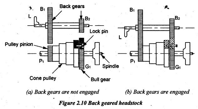
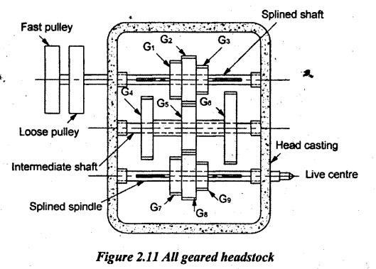
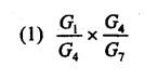
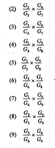
HEADSTOCK MECHANISMS There are two types of headstock driving mechanisms as follows. (a) Back geared headstock (b) All geared headstock. Back gear arrangement is used for reducing the spindle speed which is necessary for thread cutting and knurling. The back gear arrangement is shown in Figure 2.10. There is one stepped cone pulley in the lathe spindle. This pulley can freely rotate on the spindle. A pinion gear P1 is connected to the small end of the cone pulley. The gear P1 will rotate when the cone pulley rotates. Bull gear G1 is keyed to lathe spindle in such a way that the spindle rotates when the gear G1 will rotate. The speed changing can be obtained by changing the flat belt on steps of the stepped cone pulley. A bull gear G1 may be locked or unlocked with this cone pulley by a lock pin. There are two back gears B1 and B2 on a back shaft. It is operated by means of hand lever L. By shifting the hand lever L, back gears B1 and B2 can be engaged or disengaged with G1 and P1. For getting the direct speed, the back gear is not engaged. The step cone pulley is locked with the main spindle by using the lock pin as shown in Figure 2.10(a). The flat belt is changed for different steps. These three or four ranges of speed can directly be obtained. For getting slow or indirect speeds, the back gear is engaged by lever L and lock pin is disengaged as shown in Figure 2.10(b). Now, the power will flow from P1 to B1, B1 to B2 (same shaft), B2 to G1 and G1 to the spindle. As the gear B1 is larger than P1, the speed is reduced at B1. B1 and B2 will have the same speed. The speed will further be reduced at G1 because gear G1 is larger than B2. So, the speed of the spindle is reduced by engaging the back gears. All geared headstock is commonly used in modern lathes because of the following advantages. (i) It gives wider range of spindle speeds. (ii) It is more efficient and compact than cone pulley mechanism. (iii) The power available at the tool is almost constant for all spindle speeds. (iv) Belt shifting is eliminated. (v) The vibration of spindle is reduced. (vi) More power can be transmitted. The all geared headstock is shown in Figure 2.11. The power from the constant speed motor is delivered to the spindle through a belt drive. The speed changing is made by levers. The different spindle speeds are obtained by shifting the levers into different positions to obtain different gear combinations. This mechanism has the splined spindle, intermediate shaft and splined shaft. The splined shaft receives power from the motor through a belt drive. This shaft has 3 gears namely G1, G2 and G3. These gears can be shifted with the help of a lever along the shaft. Gears G4, G5 and G6 are mounted on the intermediate shaft and it cannot axially be moved. Gears G7, G8 and G9 are mounted on splined headstock spindle and it can axially be moved by levers. Gears G1, G2 and G3 can individually be meshed with the gears G4, G5 and G6. Similarly, gears G7, G8, G9 can individually be meshed with gear G4, G5 and G6. Thus, it provides nine different speeds. For example, when the gear G1 meshes with G4, G7 will be made to mesh with G4 at the same time. The speed can be obtained is Similarly, for the other combination of gears for various speeds are:1. Back Geared Headstock
2. All Geared Headstock
Manufacturing Technology: Unit II: Turning Machines : Tag: : Back Geared Headstock, All Geared Headstock - Headstock mechanisms
Related Topics
Related Subjects

Manufacturing Technology
ME3493 4th semester Mechanical Dept | 2021 Regulation | 4th Semester Mechanical Dept 2021 Regulation