Manufacturing Technology: Unit III: Reciprocating Machine Tools
Grinding
Reciprocating Machine Tools - Manufacturing Technology
Grinding is one of the abrasive processes. Grinding is a metal removing process in which the metal is removed with the help of rotating grinding wheel.
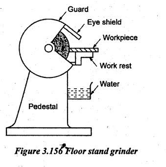
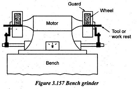
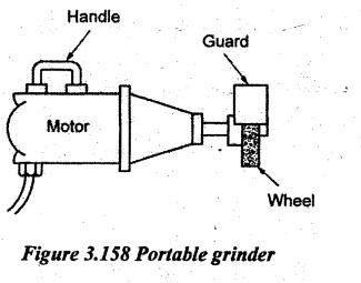
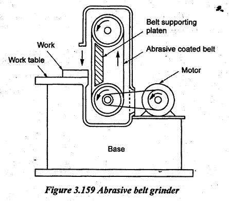
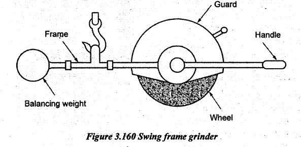
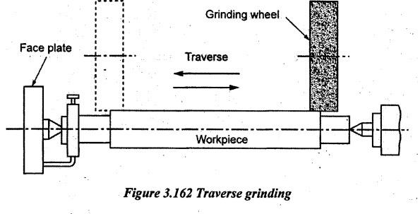
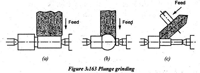
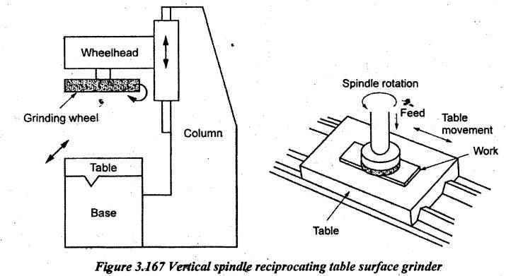
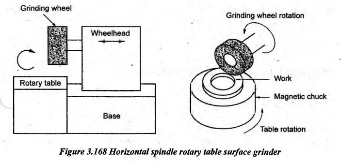
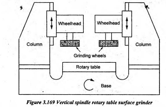
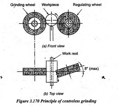
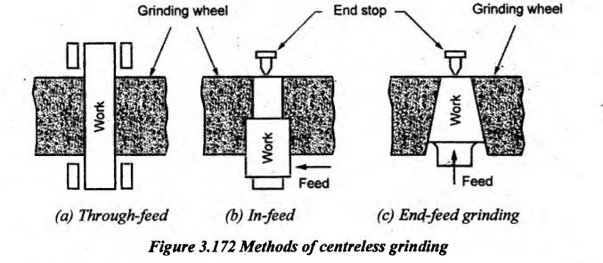
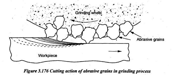
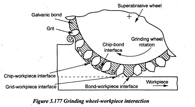
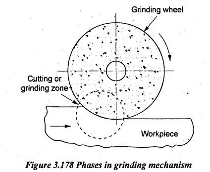
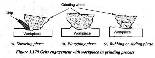
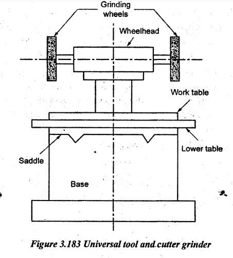
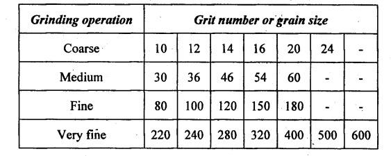
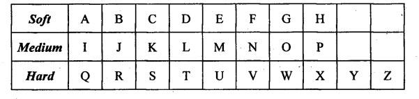
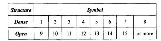
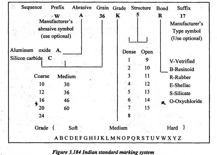
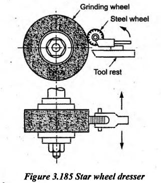
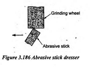
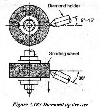
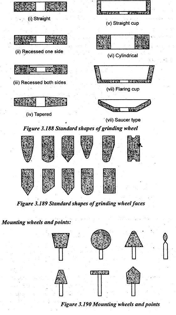
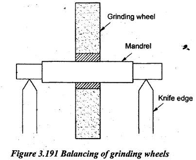
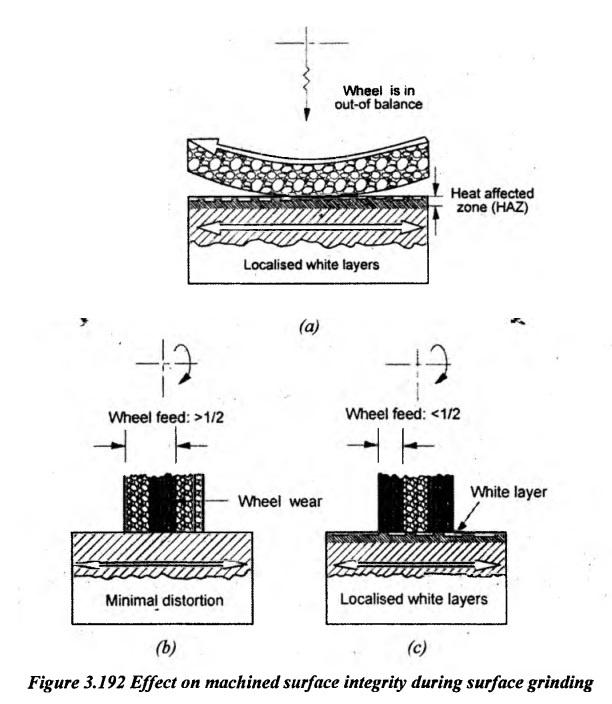
GRINDING Grinding is one of the abrasive processes. Grinding is a metal removing process in which the metal is removed with the help of rotating grinding wheel. Such wheels are made of fine grains of abrasive materials held together by a bonding material called a bond. These abrasive materials are having high hardness and high heat resistance. Grinding provides a very good surface finish with high accuracy. Therefore, it is used as a finishing operation. This process removes comparatively little material usually from 0.25 mm to 0.5 mm. While grinding, the wheel is rotated and the work is fed against the wheel. Tl.e abrasive grains which project on the surface of the grinding wheel moving with high velocity and shear off small metal particle from the workpiece. During machining, the blunt abrasive grains will be released from the wheel surface. In their place, new abrasive grains project from the surface of the wheel. This process is called self-sharpening of the grinding wheel. Grinding is mainly used for the following purposes. (i) To remove small amount of metal from workpieces and finish them to close tolerances. (ii) To obtain a better surface finish. (iii) To machine hard surfaces which cannot be machined by high-speed steels. (iv) Sharpening of cutting tools. (v) Grinding of threads. (vi) Sometimes, it is used for removing bigger stocks of metals. A grinding machine shortly called a grinder is of various power tools or machine tools used for grinding which is a type of machining using an abrasive wheel as the cutting tool. A distinguishing feature of grinding machines is the rotating abrasive tool. Grinding machine is employed to obtain high accuracy along with very high class of surface finish on the workpiece. Each grain of abrasive on the wheel's surface cuts a small chip from the workpiece by means shear deformation. Grinding is used to finish workpieces to obtain high surface quality and high accuracy of shape and dimension. The grinding machines may be classified as follows. 1. According to the type of operation a) Tool grinders b) Cut off grinders. 2. According to the quality of surface finish a) Precision grinders b) Rough grinders. 3. According to the type of surface generated a) Cylindrical grinders b) Internal grinders c) Surface grinders d) Tool grinders e) Special purpose grinding machines f) Surface finishing grinders. Grinding machines can probably be best classified according to the type of surfaces that they are used to produce i.e. rough and precision grinders. They are further classified as follows. 1. Rough grinders a) Floor stand grinders b) Bench grinders c) Portable grinders d) Abrasive belt grinders e) Swing frame grinders. 2. Precision grinders a) Cylindrical grinders (i) Centre type plain grinders (ii) Centre type universal grinders (iii) Centreless grinders. b) Internal grinders (i) Chucking type grinders (ii) Planetary type grinders (iii) Centreless grinders. c) Surface grinders (i) Reciprocating table-horizontal spindle (ii) Rotary table-horizontal spindle (iii) Reciprocating table-vertical spindle (iv) Rotary table-vertical spindle d) Tool and Cutter grinders e) Special grinders. 1. Rough Grinders Rough grinders are mainly used for removing a large amount of metal from the workpiece. Therefore, the surface finish and the accuracy in dimension are not high. A rough grinding is used for removing projections such as sprue pins from castings, grinding the projections in the forgings, finishing the weldments, sharpening of hand tool etc. The various- types of grinder used for rough grinding are described below. 2. Floor Stand Grinder It is mounted on a floor and consists of a horizontal spindle with grinding wheels mounted at each end of the motor shaft extensions. It is also known as pedestal grinder. The work is normally held by the operator in hand and pressed against the wheel to remove the material. The driving motor is placed inside the pedestal. The motor is connected to the spindle by belts. It has a guard with an eye shield for a safety purpose. A work rest is provided for supporting the workpiece while grinding. This type of grinder is used for rough grinding of tools and other small parts. 3. Bench Grinder It is similar to a floor grinder except for the size. It is smaller in size and mounted on a bench. The grinding wheels are directly mounted on the motor spindle. It has two wheels and guards similar to pedestal grinder. A work rest is provided for supporting the workpiece while grinding. Bench grinders are mainly used for grinding of hand tools and small parts. 4. Portable Grinder This type of grinding machine is very handy and it is used for cleaning castings, welded works, sheet metal works, rough works etc. It can be carried from place to place. It has a small electric motor. A small grinding wheel is attached to the end of the motor spindle. The motor is connected by a long wire to the main supply using a plug. 5. Abrasive Belt Grinder The line diagram of this grinder is shown in Figure 3.159. An endless belt having abrasive particles is running over two drums. The abrasive belt has small abrasive grains pasted to one of its sides. The bottom drum is connected to a driving motor. Workpieces may feed against the abrasive cloth by hand. There is a platen supporting the belt at its backside. This grinder is used for rough grinding of the workpiece. The accuracy in this grinder cannot be expected. The accuracy depends on the skill of the operator. Small and irregular shaped workpiece can safely be ground on this grinder. 6. Swing Frame Grinder It has about 3 m long horizontal frame suspended at its centre so as to move freely within the area of operation. One end of the frame carries the grinding wheel attached to a motor. The other end of the frame carries a balancing weight. There is a handle provided at the wheel end. This handle is used for moving the grinding wheel and applying the force on the workpiece for rough grinding. The grinder can be suspended from a jib crane. So, the grinder can be moved along the crane. It is used for snagging castings which are too heavy and large. Precision grinders are used to manufacture parts of accurate dimensions and good surface finish. The workpiece and the grinding wheel are rigidly mounted but they are adjustable according to the requirement of the machining methods. A precision grinding is applied for grinding cylinder bores, gauges, tools, cutters, machine guide ways, threads, cylindrical pins, gears, cams etc. Normally, these parts are heat-treated for improving hardness. After hardening, precision grinding is done to set the required surface finish and dimensions. The various types of precision grinders are discussed below. 1. Cylindrical Grinders The principle of the cylindrical grinder is illustrated in Figure 3.161. The workpiece is held between centres. It is rotated by a dog and a faceplate. There are four movements in a cylindrical centre type grinding. (i) Rotation of cylindrical workpiece about its axis (ii) Rotation of the grinding wheel about its axis (iii) Longitudinal feed movement of the work past the wheel face. (iv) Movement of the grinding wheel into the work perpendicular to the axis of the workpiece to give depth of cut. Although they can also be used for grinding contoured cylinders, tapers, shoulders, fillets, cams, crankshafts etc., these grinding machines are used for grinding plain cylindrical parts. 1. Types of operations performed in cylindrical grinding: Two types of grinding operations are carried out. Traverse grinding (ii) Plunge grinding. (i) Traverse grinding: This method is used when the job length is more than the width of the grinding wheel. The job is held between two centres. The grinding wheel is made to rotate in a fixed position. The rotating work is made to traverse. The rotating work longitudinally moves in both directions. It is the longitudinal feed. (ii) Plunge grinding: This method is used when the length of the workpiece is lesser than the width of the grinding wheel. Here, the workpiece need not longitudinally be fed. The grinding is done by giving only the cross feed to the grinding wheel. It is known as plunge grinding. Here, no longitudinal movement is given to the workpiece. Therefore, the table is locked. The wheel is fed till the required diameter is obtained. In Figure 3.163 (a) and Figure 3.163 (b), the wheel is radially fed which is perpendicular to the axis of the workpiece. In Figure 3.163 (c), the wheelhead is tilted at an angle. An angular feed is given through the wheel. The wheel is specially shaped. Aplunge grinding is used for grinding shoulders, stepping and various contours on the workpiece. 2. Types of cylindrical grinding: (i) Plain centre type cylindrical grinding machine: A plain centre type cylindrical grinding machine is shown in Figure 3.164. These grinding machines are used for grinding mainly cylindrical parts. They are also used for grinding parts such as tapers, fillets, contoured cylinders etc. The grinding machine consists of various parts. 1. Base: The base is the main casting that rests on the floor and it supports the parts mounted on it. On the top of the base, horizontal guide ways are set on which the table slides to give a traverse motion to the workpiece. The table drive mechanism is incorporated in the base itself. 2. Table: There are two tables such as upper table and lower table. The lower table slides on the guide ways of the bed and it provides traverse feed or longitudinal feed of the work past the grinding wheel. It can be moved by either hand or power within the limits. The adjustable dogs are provided at the side of the lower table. These dogs can be set up in a proper place to reverse the table at the end of the stroke. The upper table is mounted on the lower table and it carries headstock and tailstock. The headstock and tailstock can be adjusted according to the length of the workpiece. The upper table can be swiveled and clamped in a position over the lower table. The maximum angle of the swivel is 10° on either side. The swiveling is used for grinding tapers. 3. Headstock: The headstock supports the workpiece by means of a dead centre. The workpiece is driven by the headstock through the dog and driving pin. A separate motor is housed in the headstock to rotate the workpiece. 4. Tailstock: The tailstock can be adjusted and clamped to accommodate various lengths of workpieces. The workpiece is held in between centres of headstock and tailstock. 5. Wheelhead: The wheelhead carries a grinding wheel and rotated by a motor housed in the headstock. The wheelhead is placed over the bed at its backside. The wheelhead can be moved perpendicular to the table ways by hand or power. This movement is the cross feed. Working principle: The workpiece is held between centres. It is rotated by a dog or faceplate. The grinding wheel also rotates about its own axis in the opposite direction of work. The grinding wheel is fed by either hand or automatic mechanism towards the workpiece for successive cuts. In most of the cases, the work speed is selected between 20 and 30 surface speed meters per minute (smpm). Wheel speed is usually selected between 1500 and 2000 smpm. The depth of cut at each reversal is from 0.025 mm to 0.125 mm for rough grinding. For finishing process, it should be from 0.0125 mm to 0.0625 mm. The longitudinal feed depends on the rigidity and power of the machine which varies from 0.25 to 0.75 of the width or wheel's face. (ii) Centre type universal grinder: Center type universal grinders are widely used in tool room for grinding tools. The line diagram of this type of grinder is shown in Figure 3.165. The features of this machine are similar to those of plain grinders but in addition, it is provided with the following features. 1. The centre of the headstock spindle can be used as a live centre or dead centre. The work can be held and revolved by a chuck. It can also be held between centres and revolved. 2. The wheelhead can be swiveled in a horizontal plane in any angle. The wheelhead can also be fed in the inclined direction. 3. The headstock can be swiveled to any angle in the horizontal plane. 4. The wheelhead can also be arranged for internal grinding. Surface grinding machines are used to produce and finish flat and plane surfaces. By using special fixtures and form dressing devices, angular and formed surfaces can also be ground. The various machine parts such as machine guide ways, piston rings, valves, dies, surface plates etc. are finished by surface grinding. Heavy workpieces are clamped on the table by means of pads, strap clamps and other devices or they are held in fixtures. Small workpieces are usually held by a magnetic chuck. The various types of surface grinders are explained below. 1. Horizontal Spindle Reciprocating Table Surface Grinder The line diagram of this type of grinder is shown in Figure 3.166. It consists of a horizontal spindle carrying the grinding wheel and rectangular worktable. The table is mounted on a base. The horizontal guide ways of the base are a rectangular box made of a casting. The driving mechanisms are housed inside the base. The table reciprocates along the guide ways for giving longitudinal feed. The tabletop has T-slots for mounting the magnetic chuck or fixtures. The cross feed to the grinding wheel is given by moving the column perpendicular to the table as shown in Figure 3.166. The wheelhead is mounted on the column. It has an independent motor for driving the wheel. The wheelhead can move up and down along the vertical guide ways of the column. The depth of cut is given by the aforesaid arrangement. Working: The workpiece is clamped on the table. The trip dogs are suitably adjusted to get the correct stroke length of the table. The workpiece reciprocates under the grinding wheel. The periphery of the grinding wheel does the grinding. The cross feed is given to the workpiece after every stroke. The depth of cut is given by lowering the wheelhead. For rough grinding of the workpiece, the depth of cut may be from 0.02 mm to 0.06 mm. For finishing operation, the depth of cut may be from 0.005 mm to 0.01 mm. 2. Vertical Spindle Reciprocating Table Surface Grinder The workpiece is clamped on the reciprocating worktable using a magnetic chuck or fixture. The grinding wheel rotates about a vertical axis as shown in Figure 3.167. It may be a cup or cylindrical type for faster stock removal. It is used where the accuracy is not stringent. The longitudinal and cross feed are given through the table. The face or side of the grinding wheel cuts the metal. The wheelhead is lowered down for giving the depth of cut. This grinding machine is used for grinding flat surfaces on medium size works. 3. Horizontal Spindle Rotary Table Surface Grinder In horizontal spindle rotary table surface grinders, the workpieces are mounted on magnetic chucks or on fixtures which are slowly rotating under the rotating grinding wheel about its horizontal axis. The line diagram of this type of grinder is shown in Figure 3.168. The circular table rotates at a specific speed and the wheel can be axially fed (cross-feed). The wheelhead is lowered to give the required depth of cut. The periphery of the grinding wheel takes the cut. This machine is used for small and medium size works. 4. Vertical Spindle Rotary Table Surface Grinder This machine has all parts similar to a horizontal type machine except that the grinding wheel rotates about a vertical axis as shown in Figure 3.169. The grinding spindle is vertically mounted on the face of a column and rotates in a fixed position. The vertical spindle carries a cup type grinding wheel. The grinding wheel is lowered for giving the depth of cut. The rotary table rotates along with the workpiece. The workpiece is clamped on the table using a magnetic chuck. This grinding machine is used for grinding a large quantity of small workpieces. Centreless grinding differs from centered grinding operations in such a way that no spindle or fixture is used to locate and secure the workpiece. The workpiece is secured between two rotary grinding wheels and the speed of their rotation relative to each other determines the rate at which the material is removed from the workpiece. Centreless grinding is performed on cylindrical workpieces such as pistons, valves, rings, tubes, balls, wrist pins, drills, bushings, shafts etc. Centreless grinding can be done on both external and internal cylindrical surfaces. The principle of external centreless grinding is shown in Figure 3.170. The grinder has two wheels. A larger grinding wheel is revolving at a high speed and a small regulating wheel is revolving at a slow speed. The work rest is located between wheels. The work is placed on the work rest. The regulating wheel is fed forward forcing the work against the grinding wheel. So, the work on work rest is pressed against the grinding wheel surface. By friction, the regulating wheel makes the workpiece to rotate. The rotating workpiece is pressed between two wheels. So, the grinding wheel grinds the workpiece. The regulating wheel does not remove the metal as it rotates slowly. The line diagram of the centreless grinding machine is shown in Figure 3.171. The grinding wheel is driven by an electric motor and it rotates at a maximum surface speed of about 1850 smpm. The regulating wheel speed ranges from 33 to 130 smpm. The workpiece is placed in a floating condition between grinding wheel and regulating wheel. So, it is called centreless grinding. 1. Methods of External Centreless Grinding Basically, there are three different methods by which centreless grinding can be done. They are given below. (i) Through-feed (ii) In-feed (iii) End-feed. 1. Through-feed: It is used for the straight cylindrical workpiece such as long shafts or bars, roller pins etc. In this method, the regulating wheel is tilted at a small angle. It makes the work to move axially through the space between grinding wheel and regulating wheel. The guides are provided at both ends of the wheel and guide the movement of the workpiece. The machine usually removes 0.2 mm of stock in one pass on the diameter of the work. 2. In-feed grinding: It is similar to plunge grinding. The work is placed on the work rest against an end stop. It prevents the axial movement of the workpiece. The regulating wheel and work rest with the workpieces are moved towards the grinding wheel by hand feed as shown in Figure 3.172 (b). This method is useful to grind shoulders and formed surfaces. 3. End-feed grinding: In this method, both grinding and regulating wheels are tapered and thus, it produces tapered workpieces. The workpiece is fed lengthwise between wheels and it is ground as it advances until it reaches the end stop as shown in Figure 3.172 (c). Advantages of ventreless grinding: 1. The work is supported throughout its entire length. So, there is no chatter or deflection. 2. Size of the job can easily be controlled by a regulating wheel. 3. This process is best suited for mass production since the process is continuous and rapid. 4. An excellent accuracy and fine surface finish can be achieved as there is no distortion of the workpiece during grinding. 5. Work holding devices such as chucks, dogs, centres, mandrels are not required. 6. A wide range of components can be ground. 7. A very little skill is required for the operator. 8. Large grinding wheels can be used so that the wheel wear is minimized. Disadvantages: 1. Work with flats and keyways cannot be ground. 2. Workpieces with step and multiple diameters cannot be ground easily. 3. In hollow workpieces, there is no certainty that the outside diameter will be concentric with the inside diameter. Internal grinders are used to finish straight, tapered or formed holes to the correct size, shape and finish. There are three types of internal grinders. (a) Chucking type (b) Planetary type (c) Centreless type. 1. Chucking Type Internal Grinders In this type of grinders, the workpiece is held in a chuck and rotated about its axis. The work head is mounted at the left side of the machine. The wheelhead is mounted at the right end of the machine. The grinding wheel is rotated and at the same time, it reciprocates back and forth through the length of the hole as shown in Figure 3.173. These machines are used for grinding workpiece which can easily be held in a chuck. 2. Planetary Type Internal Grinders In this type of grinders, the work remains stationary and the rotation of wheel spindle gives an eccentric motion according to the diameter of the hole to be ground. Such type of operation is used where the work is difficult to rotate. Therefore, in this operation, the motion of the grinding wheel is in the form of the planet and hence, it is called planetary grinding. The axis of the grinding wheel rotates around a circular path about the centre of the bore to be ground. The traverse feed is given by the reciprocating motion of the workpiece. 3. Centreless Internal Grinding The external centreless grinding principle is also applied to internal grinding. In centreless internal grinding, the work is supported by three rolls. One is the regulating wheel, the second one is a supporting roll and the last one is a pressure roll. The pressure roll is used to hold the workpiece against the support and regulating rolls. The regularity roll is a rubber bonded wheel. This roll makes the workpiece to rotate. The grinding wheel directly contacts the inside diameter of the workpiece and it reciprocates about its axis for giving the feed. The depth of cut is given by moving the grinding wheel in a crosswise direction. The pressure roll is mounted to swing aside to permit loading and unloading. Grinding is a very complex material removal operation. It is the form of abrasive machining. It is a material cutting process which engages an abrasive tool whose cutting elements are grains of abrasive material known as grit. Actual grinding performance can be considered as the summation of the performance of individual grits. These grits are considered by sharp cutting points, high hot hardness, chemical stability and wear resistance. The grits are held together by a suitable bonding material to give shape of an abrasive tool. The grinding mechanism is made on the basis of the cutting-edge geometry and the kinetics involved. Each grain of abrasive functions as a microscopic single-point cutting edge and shears a tiny chip called a "cut" chip shown in Figure 3.176. In grinding process, abrasive grits on the wheel surface are of irregular shapes and are randomly positioned. The undeformed cutting depth of each grit or cutting edge in grinding is very thin, down to sub micrometre or nanometre level. The cutting chip may not form in each grit pass in the grinding zone. The grinding cutting speed is higher than that other machining process. Normally, it is 10 times higher. Compared to conventional machining, grinding differs in many ways such as the use of high wheel speeds, fine depths of cut, a large number of multiple cutting points of unknown geometry which varies continuously with time, the high negative rake angles presented by the abrasive grains. 1. Grinding Wheel and Workpiece Interaction In grinding process, the kinematic relationship between the grinding wheel and the workpiece motions applies all cutting grits on the wheel surface. The interaction of grinding wheel-workpiece is shown in Figure 3.177. The grinding wheel-workpiece interaction is divided into four stages as follows: 1. Grit-workpiece (forming chip) 2. Chip-bond 3. Chip-workpiece 4. Bond-workpiece The last three interactions require more total grinding force and power requirement except grit-workpiece interaction. In this grit-workpiece interaction stage, the formation of chip starts. So, more efforts are needed to maximize grit-workpiece interaction to promote the chip formation. The grit shape determines the grit geometry, for example, rake and clearance angle. At the same time, grits do not have definite geometry not like a single point cutting. Usually, the grit angle varies from +45° to - 60°. 2. Phases in Grinding Mechanism When the grit engages with the workpiece in an up-cut grinding shown in Figure 3.178, initially, the grit slides without cutting on the workpiece surface due to the elastic deformation of the system called rubbing phase or sliding phase. As the stress between the grain and workpiece is increased beyond the elastic limit, plastic deformation occurs. In ploughing phase, the workpiece material piles up to the front and sides of the grit to form a groove. A chip is formed when the workpiece material can no longer withstand the tearing stress in chip formation stage called cutting phase or shearing phase. Based on the energy requirement to remove material, cutting phase is the most efficient phase. Rubbing and ploughing are inefficient because they water energy to perform deformation and friction without contribution of material removal. Also, theses phases generate high temperature which leads to excessive rate of wheel wear and metallurgical damage called grinding burn on the workpiece surface. So, the energy waste for both rubbing and ploughing should be minimised because it will produce the adverse effects to the grinding performance. The grit engagement with workpiece is shown in Figure 3.179. 3. Grinding Ratio and its influencing Parameters Grinding ratio is defined as the ratio between the volume of metal removed from the workpiece to the wear of grinding wheel. In conventional grinding, grinding ratio is in the range 20: 1 to 80: 1. G ratio is a measure of grinding production and reflects the amount of work a wheel can do during its useful life. As the wheel losses material, it must be reset or repositioned to maintain workpiece size. Some grinding machines are designed for highly specialized works such as forming, gear teeth grinding, thread grinding, cam grinding, tool and cutter grinding etc. These grinders are called special purpose grinders. Some of these types are explained below. 1. Gear Teeth Grinding It is already discussed in chapter 3.8.24.4 on Page 3.156. 2. Form Grinders The grinding wheel for form grinding is so shaped that the form of the surface is to be obtained. Figure 3.180 (a) and Figure 3.180 (b) show the grinding operation of dovetail guide ways and machining of a complex cross-section. 3. Thread Grinding This is also one type of forming methods by which the thread is ground on a cylindrical surface. In this process, the principle of cylindrical grinding is used for thread grinding with a specially formed wheel that matches with the thread profile. The grinding wheel is either single or multiple rib wheels as shown in Figure 3.181. The work is mounted between centres and it is rotated at a definite speed. The ribbed grinding wheel is mounted on the wheelhead spindle and it is rotated by a separate drive. The wheel also has a longitudinal movement which is equal to one pitch of the thread per revolution of the work. Thread grinding machines must have a precision lead screw to produce the correct pitch, or lead, on a threaded part. Thread grinding machines also have a means of dressing or truing the cutting periphery of the grinding wheel so that it will produce a precise thread form on the part. 4. Cam Grinders These machines are basically cylindrical grinding machines with additional feeding and withdrawal mechanisms for the workpiece. An arrangement for grinding cams of a camshaft is shown in Figure 3.182. The grinding wheel is arranged so that it can radially be moved towards or away from the workpiece in coordination with the rotation of the workpiece. Before carrying out the operation, a small template is mounted on the headstock. A hardened steel roller in conjunction with a template actuates the movement of the whole unit to produce the desired shape. The grinding wheel is continuously in contact with the cam surface during operation. The camshaft has simultaneous rotary and oscillating motions as well as an axial motion to obtain a fine surface finish. 5. Tool Post Grinder It is used for miscellaneous and small grinding works on a lathe. The grinding wheel is held on the tool post of a lathe and fed across the work. The regular longitudinal or compound rest feed being used. A common application of tool post grinder is the truing of lathe centres. 6. Disc Grinder These grinders rapidly remove the stock and finish the flat surfaces by the sides of disc wheels. A single horizontal or vertical spindle disc grinder is used for repetitive work by hand operation or with a simple fixture. The double horizontal spindle is mostly used for production operations. The work up to 350 mm in length can be ground in opposed wheel grinders with wheels up to 750 mm. 7. Tool and Cutter Grinder As the name implies, this type is mostly used to sharpen and recondition the various types of cutters such as single point cutting tools, milling cutters, drills, taps, hobs etc. By using a special attachment or fixture, this machine can also be used for grinding die, jig, fixture, flat surface, cylindrical, internal surfaces etc. They are classified into two groups according to the purpose of grinding. (i) Single purpose and cutter grinders (ii) Universal tool and cutter grinders. Single purpose grinders are used for grinding tool such as drills, tool bits etc. A universal tool and cutter grinders are used for sharpening various other cutters such as reamer, milling cutters, special drills, counter bores and special cutters. Figure 3.183 shows the principle parts of a universal tool and cutter grinders. 1. Base: The base is a heavy box type casting which provides the stability and rigidity. 2. Saddle: The saddle is directly mounted at the top of the base. It moves on antifriction bearings on hardened guide ways. It provides the cross movement. The column supporting the wheelhead is mounted on the saddle and it can be moved up or down and swiveled to either side. 3. Table: There are two tables-upper or worktable and lower table. The upper table swiveled on the lower table. that longitudinally slides on the saddle. The workpieces are clamped on the worktable by using T-slots provided at the top surface. 4. Headstock and Tailstock: The headstock and tailstock are mounted on either side of the table similar to those on a cylindrical grinder. 5. Wheelhead: The wheelhead is mounted on a column on the back of the machine. It can be moved up and down and swiveled to either side of the column for varied set ups. Three types of grinding wheels are used on this machine. (i) The straight or disc-shaped wheel (ii) The cup type (iii) The disc type. The fluid used during grinding or dressing to cool, lubricate, and clean the work, wheel and diamond dresser are called cutting fluids. Sometimes it is also called grinding fluid. It is a substance, generally liquid, used to enhance workpiece characteristics and reduce costs in a metal cutting operation. Cutting fluids may be oil-based fluids, water-oil emulsions, or chemicals in water solution. Lard oil is excellent cutting oil but it is relatively expensive. So, it is mostly used in combination with mineral oils. Mineral oils are used for grinding non-ferrous alloy for low duty machining operations. They are generally extracted from petroleum oil. This group includes paraffin. Emulsifiable oil (soluble oil) consists of water with the mixture of 2-5% of oil in an extremely finely distributed form. The concentration used depends on the severity of the machining operation. The more severe the operation the more oil is added to the solution. The manufacturer's recommendation should be used in preparing the fluid. Water solutions are liquids that consist of water with synthetic additives in order to increase its wetting performance and prevent corrosion. Such fluids contain no oil and provide good cooling performance but poor lubrication performance. Synthetics (chemical fluids) are solutions of organic and inorganic chemicals dissolved in water. Plain fluid solutions have reasonable rust inhibition, good cooling and low lubricity and they are used for grinding operations. Other types include additives for surface wetting properties and improved lubrication and EP (extreme pressure) properties. Sulphur or chlorine additives may also be used as EP additives. These are used for a wide range of machining operations. Cutting oils are composed of a mineral oil base with EP-type additives. Cutting oils provide effective lubrication but poor cooling. Water solutions are most suitable with diamond wheels during grinding. Emulsions are used nowadays for the majority of grinding operations because they are ecologically beneficial and perform adequately. The functions of cutting fluids are as follows: (i) It cools the workpiece. (ii) It acts as a lubricant and reduces friction between chips, workpiece and grinding wheel. (iii) It removes chips from the contact area. Grinding wheels are made up of small abrasive particles held together by bonding materials. Thus, it forms a multi-edge cutter. 1. Types of Abrasives in Grinding Wheel Abrasive is a hard material. It is used to cut or wear away other materials. Small sizes of abrasive particles are used in grinding wheels. They are called abrasive grains. Abrasives may be classified into the following two types. (i) Natural abrasives, and (ii) Artificial abrasives. 1. Natural abrasives: These are produced by uncontrolled forces of nature. These are obtained from mines. The following are the natural abrasives. a) Sandstone or solid quartz. b) Emery (50 to 60% crystalline Al2O3 + Iron oxide). c) Corundum (75 to 90% crystalline Al2O3 + Iron oxide) d) Diamond. Natural abrasives lack the uniformity of properties and the reliability has largely been replaced by manufactured or artificial abrasives. 2. Artificial abrasives: These are manufactured under controlled conditions in closed electric furnace in order to avoid the introduction of impurities and to achieve the necessary temperature for the chemical reaction to take place. These abrasives have better cutting properties and higher efficiency than natural abrasives. The various manufactured abrasives are: a) Aluminium oxide b) Silicon carbide c) Artificial diamond d) Boron carbide e) Cubic boron nitride. (a) Aluminium Oxide (Al2O3): It is the crystalline form of aluminium oxide. This abrasive carries very hard and tough grains having sharp cutting edges. It is manufactured by fusing mineral Bauxide in an electric arc furnace mixed with coke and iron scrap. Here, iron scrap acts as a flux. After fusing, it is crushed, washed and treated with alkalis. Again, it is washed and finally ground. Aluminium oxide is tough and less brittle. It is used for grinding materials of high tensile strength such as high speed steel, malleable iron, wrought iron etc. The common trade name for this abrasive is 'Alundum', 'Aluminium Oxide', 'Aloxide and 'Borolon'. Aluminium oxide is represented by a letter A. (b) Silicon carbide: It is made from silicon dioxide, coke, sawdust and salt. The ingredients are thoroughly mixed and heated in an electric furnace about 2000°C for 34 hrs. The mass under the-action of intense heat fuses and the following chemical reaction takes place. SiO2 + 3C = SiC + 2CO The silicon carbide mass is crushed, washed and treated with alkalis. It is again washed and finely ground into small particles. Silicon carbide is hard and brittle. It is used for grinding materials of low tensile strength such as grey cast iron, brass, copper, aluminium etc. The common trade name for this abrasive is 'Silicon carbide' 'Carborundum', 'Crystolon' and 'Electron' etc. It is represented by a letter C. In general, the physical properties of aluminium oxide are compared with silicon carbide. as follows: (i) Silicon carbide is harder than aluminium oxide. (ii) Aluminium oxide can withstand greater stresses than silicon carbide. (iii) Aluminium oxide is tougher than silicon carbide. (c) Artificial diamond: Artificial diamond is a form of pure carbon which is mainly used for truing and dressing other grinding wheels for sharpening carbide tools, and for processing glass, ceramics and stone. (d) Boron carbide (B4C): It is harder than silicon carbide but not as hard as diamond. It is produced from coke and boric acid at tremendously high temperatures in an electric furnace. Boron carbide is mainly used for grinding and lapping very hard metals, hard alloys, glass and jewels. (e) Cubic boron nitride: It is another synthetic abrasive that is harder than either aluminium oxide or silicon oxide. It is a combination of boron and nitrogen. Boron nitride is the second hardest substance ever developed by man or nature. It is used for grinding HSS cutters, grinding tool-steel, punch-press dies, grinding some hardenable stainless steels and for internal grinding of all ferrous metals. Bond is an adhesive substance which holds the abrasive grains together to form the grinding wheel. The bonds must sufficiently be strong to withstand the stresses of high speed rotating grinding wheel. There are various types of bonds used and their choice depends on operating conditions of the abrasive tool such as grinding speed, pressure on the tool, heat formation in the grinding zone etc. Bonds are classified into the following two types. (i) Organic bonds (ii) Non-organic bonds. Metallic, vitrified and silicate bonds are non-organic. Resinoid, rubber, shellac and oxychloride bonds are organic. The various bonding procedures are discussed below. 1. Vitrified bond: Vitrified bond is made of clay and water. The abrasive grains and fusible clay (also called 'felspar') are thoroughly mixed together with sufficient water to make the mixture- uniform. This mixture is placed in moulds to get the shape of grinding wheel and it is dried at room temperature. These wheels are then fed into a furnace and allowed to remain for few days at a temperature of about 1260°C. This process is known as fusing and it provides uniform distribution of the bond throughout the wheel. Then, these wheels are trimmed to the required size. Vitrified bonds are used most extensively. Advantages: 1. It is made porous and it enables a quicker stock removal. 2. It is not affected by water, oil, acids and alkaline. 3. The bond itself is very hard and acts as an abrasive. 4. The structure of the wheel is uniform due to wet mixing of the different constituents. Disadvantages 1. The process of manufacture is very slow. 2. Cracks may develop in large wheels during fusing. 3. Wheels over 750 mm diameter cannot easily be produced. 4. High temperature in the oven tends to make the abrasive grains weak. 5. A proper control during fusion becomes difficult. 2. Silicate bond: Silicate wheels are made by mixing abrasive grains with silicate of soda. The mixture is moulded in a mould and dried for several hours. After drying, the moulded material is kept in a furnace at about 260°C for 20 to 80 hrs. Silicate bonded wheels are light grey in colour. These wheels are having a fairly high tensile strength. The specific purpose of these wheels is that where a cool cutting action with less wear is needed in grinding the edges of the heat- treated steel cutting tools. Advantages: 1. It is more rapid process than the vitrified bond. 2. There is no tendency to weaken the grains because of low temperature. 3. Fusing is better controlled and hence, it makes a more reliable bond. 4. Large wheels up to 1500 mm diameter can easily be produced. 5. The cutting action of the wheel is smoother and cooler. Disadvantages: 1. Extra hard wheels cannot be produced with this bond. 2. Wear of the wheel is high. 3. Harder grades of this bond do not provide a free cutting action. 3. Resinoid bond: Resinoid bonding is produced by mixing abrasive grains with synthetic resins. The mixture is rolled into the desired shape and baked at a temperature of 210°C to 250°C for few hours. At this temperature, the resin sets to hold the abrasive grains in a wheel form. Resinoid bonded wheels are strong, elastic and permit high peripheral speeds but they are destroyed by alkaline cooling fluids. It can be avoided by impregnating the wheel with paraffin. These wheels normally operate at surface speeds in the region of 300 m/min. They are particularly suitable for the use in grinding steel, cast iron and malleable iron castings. 4. Rubber bond: The abrasive grains are mixed with liquid rubber and sulphur. The mixture is rolled into sheets of the required thickness. The wheels are then cut and placed in preheated moulds and vulcanized under pressure. These wheels are quite strong, close-grained and they can be made into very thin sections. They are mainly used where a very high-class surface finish is the primary requirement. The rubber-bonded wheels are also used as regulating wheels in centreless grinding. During the operation, water can safely be used as a coolant but caustic soda and oil should not be used. 5. Shellac bond: Shellac bonded wheels are made by mixing the abrasive grains with shellac in a mixture. Then, the mixture has been rolled or pressed into the desired wheel shape. They are hardened by baking for several hours at about 160°C. Shellac bond wheels. are strong but it possesses some elasticity as rubber wheels. These wheels produce high surface finish and they are used for grinding parts such as camshafts and mill rolls. Very thin wheels are used for cutting off operations. 6. Oxy chloride bond: This bond is produced by mixing abrasive grains with oxide and chloride of magnesium. This mixture is pressed into moulds and dried. It is heated in a furnace. These wheels are less brittle and less sensitive to side loads as compared to vitrified bond wheels. This type of wheel ensures a cool cutting action. So, grinding is done in dry condition. These wheels are affected by acidic solutions, dampness and sudden changes in temperature. This bond is used for making disc-shaped wheels. Different types of bonds used in grinding are represented by different symbol as shown below: Vitrified bond - V Silicate bond - S Resinoid bond - B Rubber bond - R Shellac bond - E Oxychloride bond - O 1. Grit Number and Grain Size It refers to the actual size of the abrasive particles. The grain size is denoted by the grit number. Grit number is equal to the number of meshes in 254 cm of a sieve through which the grains can pass through. Larger is the grit number, smaller will be the grain size (fine grit) and vice-versa. For rough grinding, coarse-grained wheels (smaller grit number) are used. For finish grinding, fine-grained wheels (large grit number) are used. Table 3.4 shows the grain size used for coarse grinding to very fine grinding operations. Table 3.4 Grain size used for grinding operations 2. Grade Grade or hardness indicates the strength with which the bonding material holds the abrasive grains in the grinding wheel. It does not refer the hardness of abrasive grains. So, the grade of the wheel has nothing to do with the hardness of the abrasive particles. The degrees of hardness are specified by the use of letters of the alphabet. 'A' indicates the softest grade whereas 'Z' indicates the hardest grade. A soft graded wheel will readily release the abrasive particles. When the hard metal is grinding, the abrasive grains will be blunt quickly. When the soft grade wheels are used here, the blunt grains are readily released. New sharp grains will project from the wheel surface. These grains will effectively cut the hard material. Therefore, for grinding hard material, soft wheels are used. For grinding soft material, hard grade wheels are used. The different grades of grinding wheels are shown in Table 3.5. Table 3.5 Grades of grinding wheels 3. Structure of Wheels This term denotes the spacing between abrasive grains or in other words the density of the wheel. The structure of grinding wheel is designated by a number. Higher is the number, wider will be the spacing. When the spacing is small, the structure is called dense structure. When the spacing is wide, the structure is called open structure. The numbers are given in an ascending order from dense to wider structure. Table 3.6 indicates the two types of the structure with their numbers. Table 3.6 Structure of grinding wheels The standard marking system is shown in Figure 3.184. An Indian standard Institution (IS: 551-1954) has specified a standard system of marking the grinding wheels. According to this system, the following elements are represented in a definite order. 1. Type of abrasives 2. Grain size or grit number 3. Grade of the wheel 4. Structure 5. Type of bond 6. Manufacturer's code. The selection of a proper grinding wheel is very important for getting the best results in grinding work. A wheel may be required to perform various functions such as quick removal of stock from the material, give a high-class surface finish and maintain close dimensional tolerances. A single wheel will fail to meet all requirements. Therefore, it is necessary that the proper grain size, bond, grade, strength, shape and size of the wheel should be selected to meet the specific requirements. The following are the factors upon which the above selection depends on. (i) Constant factors (ii) Variable factors. These are described below. 1. Constant Factors 1. Physical properties of material to be ground: Materials of high tensile strength such as steel, tough varieties of bronze and other- materials are the best ground with aluminium oxide wheels. Materials of low tensile strength such as soft bronze, case hardened and chilled cast iron and aluminium are ground with silicon carbide wheels. A hard wheel is used for soft materials and a soft wheel is used for hard materials. A close spacing is required for hard and brittle materials and wide for soft and ductile materials. 2. Amount and rate of stock to be removed: It involves both accuracy and surface finish. A coarse grain and wide spacing are used for fast and rough cutting. A fine grain and close spacing are used for the finishing. 3. Area of contact: The area of contact between wheel and work affects the pressure over the number of cutting points and therefore, it influences the selection of wheel. When the contact area is small, fine grain and close spacing will be useful. When the contact area is larger, coarse grain and wide spacing will be useful. 4. Type of grinding machine: Heavy and rigidly constructed machines take softer wheels than the lighter and more flexible types. The combination of feeds and speeds on precision machines may affect the grade of the wheel desirable for the best results. 2. Variable Factors 1. Work speed: The speed at which the workpiece traversed across the wheel face is called work speed. When the work speed is higher, the greater will be the wear and tear of the wheel. So, the hard wheels should be selected. If the work speed is low, the wheel wear will also be low and therefore, the soft wheel should be selected. However, it lowers the hardness of workpieces. Most of the grinding machines are provided with variable speed mechanisms. As the diameter of the wheel decreases, the work speed will need to be increased accordingly to provide optimum working conditions. 2. Wheel speed: The speed of grinding wheel is influenced by the grade and bond. If the wheel speed is higher, a soft wheel should be selected. If the wheel speed is lower, a hard wheel should be selected. When the wheel speed is up to 2000 m/min, the vitrified bonded wheels are used. When the speed is more than 2000 m/min, rubber, shellac and resinoid bonded wheels are used. 3. Condition of the grinding machine: The heavy, rigid and well-maintained machine can use the soft grade wheels. The light and poorly maintained machine should use hard wheels. When the grinding is done in the dry condition, a soft wheel should be selected. When the grinding is done in wet condition, a hard wheel should be selected. 4. Personal factor: The skill of the workman is another variable factor which should be considered in selecting the wheel. An unskilled worker cannot handle soft wheels. Thus, an unskilled worker should be allowed to work on hard wheels. Three mechanisms are recognized as the principal causes of wear in grinding wheels: (i) Grain fracture (ii), Attritious wear and (iii) Bond fracture. Grain fracture occurs when a portion of the grain breaks off but the rest of the grain remains bonded in the wheel. The edges of the fractured area become new sharp cutting edges on the grinding wheel. This makes the grinding wheel self-sharpening, a unique property of a cutting tool. Attritious wear involves dulling of the individual grains, resulting in flat spots and rounded edges. Attritious wear is analogous to tool wear in a conventional cutting tool. Bond fracture occurs when the individual grains are pulled out of the bonding material. Bond fracture usually occurs because the grain has become dull due to attritious wear and the resulting cutting force is excessive. Sharp grains cut more efficiently with lower cutting forces; hence, they remain attached in the bond structure. During grinding operation, the grains of the wheel are subjected to wear and the wheel loses its cutting capacity. Grinding wheels are dressed to restore their cutting capacity which is lost by the phenomenon of loading and glazing. During the operation, the chips formed get entrapped in the inner granular space of abrasive particles. It is called loading and it results to an inefficient cutting operation. When the bond of the abrasive is very hard, it does not dislodge an abrasive particle. Therefore, the surface of the wheel becomes smooth and gets a glassy like appearance. It is known as glazing of the wheel. It is the process of loading and breaking away the glazed surface so that new sharp abrasive particles are again present to work for efficient cutting is called dressing. The dressing is done using the tool called dresser. There are various types of dressing tools available as follows. a) Star wheel dressing tool b) Round abrasive stick c) Diamond dressing tool. Figure 3.185 shows dressing grinding wheel using a star wheel dresser. Star wheel is a steel wheel having hardened teeth on the periphery. The dresser is guided by the tool rest. The grinding wheel runs at a slow speed. The dresser is pressed against the face of the revolving wheel and moved across the face to dress the surface. This type of wheel dresser is used for grinding coarse grain abrasive wheels. A round abrasive stick type of dressing tool consists of steel filled with a bonded abrasive. The end of the tube is held against the rotating grinding wheel and it moves across the face as shown in Figure 3.186. The grinding wheel used for precision and high finish grinding is dressed by a dresser having a diamond tip. The diamond tip dresser is held in a holder and moved across the width of the rotating grinding wheel. Only the pointed tip of the diamond does the dressing. The holder is inclined at an angle shown in Figure 3.187. A very light material is taken in diamond dressing. Truing is the process of trimming the cutting surface of the wheel to run true with the axis. By truing, the cutting surface of the worn out wheel can be shaped to the original form. It is also used to produce the required contour for form grinding. Truing is done with a diamond-truing tool. The process is similar to dressing. Grinding wheels are manufactured in various standard shapes. The different shapes of grinding wheels are as shown in Figure 3.188. A straight, recessed on one side and recessed on both sides of wheels are used primarily for grinding external or internal cylindrical surfaces and plain surface grinding. The cylinder-shaped wheel is, used for producing flat surfaces and the grinding being done with the end face of the wheel. Straight cup wheel is used for grinding flat surfaces by traversing the work past the end or face of the wheel. A flaring cup wheel is used for tool sharpening. Grinding wheels tapered on two sides are used for grinding the gear teeth and threads. Dish or saucer types are used for grinding tool saws. The straight grinding wheels can be obtained with a variety of standard faces. Some of them are shown in Figure 3.189. They are small grinding wheels of different shapes. They are attached to metal shanks which can be inserted in the chucks of portable high-speed electric motors. Figure 3.190 shows some mounted wheels and points. Balanced tools and tool holders are required to obtain the full potential of modern tool grinding machines. So, the use of high speed and unbalanced grinding wheels is not compromised both on quality and productivity. When grinding wheels rotate at high speeds, the wheel will not rotate with correct balance. The grinding wheels are balanced by mounting them on test mandrels as shown in Figure 3.191. The wheel along with the mandrel is rolled on knife edges to test the balance and corrected. Surface integrity is the surface condition of a workpiece after completing a particular manufacturing process. In grinding process, the surface integrity of ground specimen is analysed. Starting from an initial state of the workpiece, the cutting processes influence the surface, subsurface and the properties of the machined component. Besides the process itself, the initial state of the workpiece and the surroundings are important for surface integrity. The concentrated energy consumption at the contact region of a machining process can be divided into mechanical, thermal and chemical effects which lead to differing intensities of surface property alterations. Two aspects are involved in surface integrity such as topography characteristics and surface layer characteristics. The topography consists of surface roughness, waviness, errors of form and flaws. But the surface layer characteristics alter the plastic deformation, residual stresses, cracks, hardness, over-aging, phase change, recrystallization, inter-granular attack and hydrogen embrittlement. But in the case of the conventional manufacturing process, the local plastic deformation is sustained by the surface layer. The following factors influence workpiece surface topographies produced by grinding: • Workpiece material - Harder materials allow finer finishes • Type of wheel - Fine grains yield finer finishes • Dressing procedure - Improperly dressed wheels will damage the work surface • Feed rate - Finer finishes are obtained with slower feed rates • Machine rigidity - Older, worn machines yield a poor quality finish • Wheel condition - Clogged wheels cannot produce a good finish • Lubricant cleanliness Coolant filtration, removes waste that could damage workpiece surface. Generally, a good guide for the selection of the type of wheel with respect to the grinding conditions for obtaining efficient workpiece output and surface topographies are as follows: • When the harder workpiece material is to be ground, the softer wheel is used. • If the angle of contact is larger, the softer wheel is selected to either internal or external cylindrical and centerless grinding operations. • If the grinding machine is rigid, the softer wheel should be used. • When the wheel speed is high, the softer wheel can be used as the work moves a relatively small distance while the abrasive grains pass. Hence, its grinding forces are low. The result of all of these variables in the grinding process will be to introduce inconsistent surface integrity effects in combination with the range of residual stresses, depending on whether the grinding process is gentle or abusive. The abusive grinding significantly increases residual stresses in the workpiece surface layers. Under an abusive grinding condition, the dominant feature will be of a thermal nature in combination with tensile stresses in the localized surface layers. Equally, if a gentle grinding condition occurs with the abundant amount of coolant present, then reduced friction results and it tends towards the mechanical stresses, promoting a compressive residual stress in the subsurface. Figure 3.192 and Figure 3.193 illustrate the effect on machined surface integrity during surface and cylindrical grinding of high-strength steels and alloys. It means, there is a white layering present in the subsurface regions of both surface and cylindrical grinding operations. Even of the selection of wheel, workpiece material and associated cutting parameters are optimized, then if the wheel is not self-sharpening and the wheel wear pattern is towards the outer edges, rather than at the centre of the wheel's width, it will 'glaze'. A glazed wheel will introduce abusive grinding and in its worst condition, it can become 'loaded with totally inefficient cutting by further damaging the workpiece surface integrity. Therefore, under either a glazed or loaded wheel local hardness will increase. Also, the white layering tendency occurs which further degrades the workpiece surface texture and integrity.1. GRINDING MACHINES
2. CLASSIFICATION OF GRINDING MACHINES
3. Precision Grinders


4. SURFACE GRINDERS

5. CENTRELESS GRINDERS

6. INTERNAL GRINDERS


7. GRINDING MECHANISMS
8. TYPICAL APPLICATIONS OF GRINDING MACHINES


9. CUTTING FLUIDS IN GRINDING
10. GRINDING WHEELS
11. TYPES OF BONDS
12. SPECIFICATION OF GRINDING WHEEL
13. MARKING SYSTEM OF GRINDING WHEEL
14. SELECTION OF GRINDING WHEELS
15. WEAR MECHANISM OF GRINDING WHEEL
16. GLAZING AND LOADING OF GRINDING WHEEL
17. DRESSING OF GRINDING WHEEL
18. TRUING OF GRINDING WHEEL
19. SHAPES OF GRINDING WHEEL
20. WHEEL BALANCING OF GRINDING WHEEL
21. SURFACE ROUGHNESS OBTAINABLE OR CONCEPTS OF SURFACE INTEGRITY

Manufacturing Technology: Unit III: Reciprocating Machine Tools : Tag: : Reciprocating Machine Tools - Manufacturing Technology - Grinding
Related Topics
Related Subjects

Manufacturing Technology
ME3493 4th semester Mechanical Dept | 2021 Regulation | 4th Semester Mechanical Dept 2021 Regulation