Manufacturing Technology: Unit III: Reciprocating Machine Tools
gear generation principle and methods
Reciprocating Machine Tools - Manufacturing Technology
Gear generation is based on the fact that any two involute gears of the same module will mesh together.
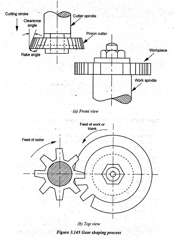
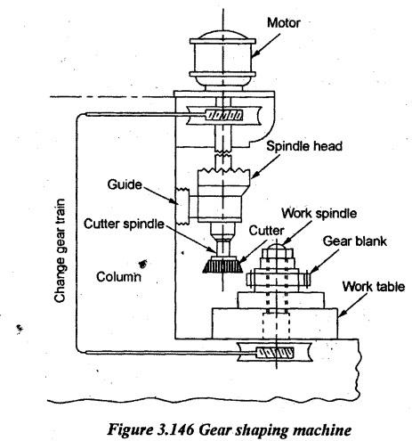
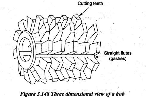
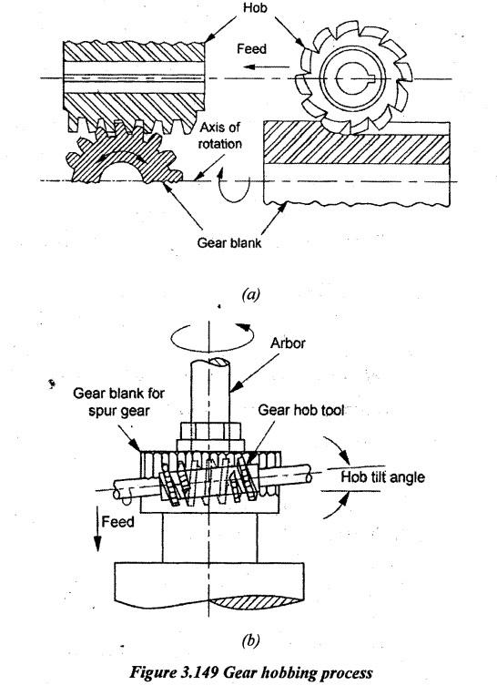
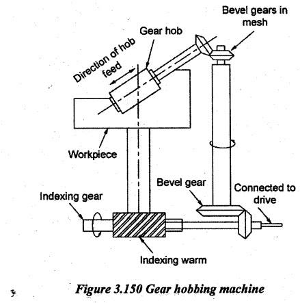
GEAR GENERATION PRINCIPLE AND METHODS Gear generation is based on the fact that any two involute gears of the same module will mesh together. Here, one of the meshing gears is made as the cutter. The other gear rotates and reciprocates along the width of the gear blank. Due to the relative rolling motion of cutter and the blank, gear teeth are generated on the gear blank. Generally, gears may be generated by a rack cutter or by a pinion cutter or a hob. By this gear generation method, the profile can accurately be produced similar to a cutter gear. The common gear generating processes are given below. 1. Gear shaping process 2. Gear planing process 3. Gear hobbing process. Gear shaping is one of the generation methods used for cutting cylindrical gears. Gear shaping is done on a special type of machine called gear shaper. Here, a pinion type of cutter as shown in Figure 3.145 is used. The cutter is ground with the top rake and clearance angles. A hole is provided in the centre portion of the cutter for mounting on a stub arbor or spindle of the machine. Two types of cutters are used such as disc type and shank type cutters. Both axes of cutter and blank are parallel. After loading the work, the cutter is radially fed into the blank to give the depth of cut. The cutter and work spindle are separately connected with gear trains. It gives the correct relative speed of rotation to these two spindles. So, the rotation of the cutter generates the tooth profile. The rolling movement is continued until all teeth on the blank are cut. During return stroke, the work is relieved from the cutter by a suitable mechanism. It is done to avoid the rubbing of the cutter over the cut surface. The various movements obtained from gear shaper are given below. 1. Rotary motion of the cutter and blank 2. Radial feed of the cutter towards the blank 3. Vertical reciprocating motion of the cutter 4. Withdrawal motion of the blank away from the cutter during return stroke. Figure 3.146 illustrates the basic components of the gear shaping machine. 7. The blank is indexed for the next cut. 8. The same procedure is repeated again and again. Applications: Gear planning is used to cut external spur gear and helical gear. Advantages: 1. Any given module can be cut using a single cutter. 2. The rate of production is higher when compared to formed cutter method. 3. It is a simple, flexible and accurate method of generating gears. Limitations: 1. Internal and worm gears cannot be produced. 2. Due to stepping back of the cutter, the time required to generate gears will be high. The process of generating a gear by means of a multipoint rotating cutter called hob is known as hobbing. The hob has helical threads. It looks similar to a worm gear having a number of straight flutes all around its periphery parallel to its axis as shown in Figure 3.148. Cutter having grooves is made with proper rake angle and clearance angle. The hobs may be either a single threaded or a multi-threaded part. In gear hobbing operation, the gear blank is niounted on a vertical arbor but the hob is mounted on a rotating arbor. The hob is rotated at a suitable rpm and simultaneously fed to the gear blank. The gear blank is also kept as revolving. Both hob and blank are made to rotate similar to a worm and worm gear in a mesh. The rotating hob at suitable cutting speed is fed against the blank. The motion of both gear blank and hob are maintained continuously and steady. One rotation of the hob makes one tooth on the gear blank. The process of gear hobbing is illustrated in Figure 3.149. Three important parameters are to be controlled in the process of gear hobbing such as indexing movement, feed rate and the angle between the axis of gear blank and gear hob. A schematic diagram of the setup of a gear hobbing machine is illustrated in Figure 3.150. The, axis of the hob is set at an inclination equal to the helix angle of the hob with the vertical axis of the blank. If a helical gear is to be cut, the hob axis is set at an inclination equal to the sum of the helix angle of the hob and the helix angle of the helical gear. A proper gear arrangement is used to maintain the rpm ratio of gear blank and hob. To cut parallel teeth, the hob axis is tilted through the hob lead angle (α). Here, α = 90° - α1 where α1 - helix angle of the hob thread. For cutting helical gears, the axis of the hob should be inclined to horizontal by ' α'. If the helix of hob and the helix of the gear to be cut are different, ⸫ Lead angle, α = θ + (90° - α1) If the helix of hob and the helix of gear to be cut are both right-handed or both left- handed, ⸫ Lead angle, α = θ - (90°- α1) Where θ - Helix angle of the helical gear to be formed α1 - Helix angle of the hob. Applications: Hobbing is used for generating spur, helical and worm gears. Advantages: 1. Using a single hob, any number of teeth of the same module can be produced. 2. Spur and helical gears can be produced using the same hob. 3. Several gear blanks mounted on the same arbor can be processed simultaneously. 4. It can be used in mass production. 5. Perfect tooth profile can be obtained. 6. It is a fast and continuous process. Therefore, it is an economical process as compared to other gear generation processes. 7. Lower production cycle time, i.e. faster production rate. 8. The process is automatic which reduces the cost of labour. Limitations: 1. Internal gears cannot be generated. 2. Hobbing process cannot be applied very near to shoulders.1. Gear Shaping
3. Gear Hobbing
COMPARISON OF GEAR SHAPING WITH GEAR HOBBING PROCESSES

Manufacturing Technology: Unit III: Reciprocating Machine Tools : Tag: : Reciprocating Machine Tools - Manufacturing Technology - gear generation principle and methods
Related Topics
Related Subjects

Manufacturing Technology
ME3493 4th semester Mechanical Dept | 2021 Regulation | 4th Semester Mechanical Dept 2021 Regulation